Laser Jammer Install Locations
 03-20-2005, 05:54 AM
#21
Contributors
Thread Starter

Join Date: Mar 2005
Location: U.S. of A.
Posts: 170
Likes: 0
Received 0 Likes
on
0 Posts
My Ride: 2005 545, Titanium Gray II, 6 Spd, CWP, Sat, LPP Laser Defense, V1 (hard-wired), iPod, 38% ceramic tint, CDV delete, H&R Street Performance Coil Overs, Forced Air Induction, DriveData Pro Camera System (4 cams), M5 Front Bumper
Originally Posted by CRRobert' date='Mar 20 2005, 12:27 AM
Have not started to run stuff yet, would get caught in the middle and need the car. 
[snapback]103959[/snapback]
I had wires dangling around for days while I worked out some of the little nuances. I still have not wired the power switch for the Lidatek. I pondered several ideas as I don't like the switch it comes with - too suspicious looking and no great place to locate it.
Instead I settled on one from Radio Shack that looks like it will blend in very well on the side of the drivers seat, embedded in the seat memory controls. This presumes that there's enough room in there. I hope to investigate later today. If it works this will be the subject of another post when I'm done.

Regarding the wiring from rear to front for the LE-30, I'll describe how I did it. It's actually quite straight-forward, but requires some patience a few hours when you won't be interrupted.
You will need 2 color coded wires - I'd suggest 20 gauge or lower. Make them about 20 feet long to start out. You should need less, but better too much than too little since you can just cut it when you're done. I used 16 gauge because I needed 4 wires (including 2 for my rear shelf V1 install), and there's plenty of good quality 4 by 16-gauge speaker wire out there, which was perfect.
Tools and Parts Needed
- 2x 20 foot 20 gauge or lower wires (diff colors)
- Philips head screw driver
- Electrical tape
- 12-volt voltage tester
- Fish tape / coat hanger / fiberglass fish rod
- Flat head screwdriver
- Wire spade plug or similar device
You may also need
- Ratchet with some metric sizes (8mm - 12mm should do it)
- Wire crimp tool or pliers
On another note, under no circumstances should you disconnect the battery while performing any electrical work on your E60. If you do, you'll probably need to get it towed to your nearest dealership.
The drive-by-wire steering system has a mechanical emergency system built in. The shaft is suspended by 2 large magnets. If power to the car fails, guess what? No magnetic power. A shaft is immediately dropped down into the steering assembly. Bye-bye active steering.
1. First Things First
First off, please see my instructions elsewhere in this topic to remove the back seat and trunk panels (also in its own topic here: V1 Install - Rear Parcel Shelf).
2. Stick it Somewhere
Take some electrical tape and adhere a foot or two of wire to the inside wall above the rear fuse panel, above the battery. This is just to keep them here while you run the wires through the interior. You can cut these down to size later on.
3. No Loose Wires
I suggest using electrical tape to tie the 2 wires together in a few places (every 1-2 feet) just to keep them tight. You should just do this as you go along. There is no need to do this the whole length of your wiring run - just in the trunk area where they are likely to move around if you don't.
4. Nip and Tuck
Just inside the trunk lid, in the interior of the rear wall there is a short plastic panel (maybe 6-9" tall) that goes down to the floor. Just tuck your wires underneath this panel, along the floor of the trunk - coming from the passenger side over to the drivers side. Shove them up in there and they still stay put.
Here's a view from inside the trunk (from above) as the wires go into the drivers side of this panel.

Here's a pic of what it looks like coming out the drivers side of this panel.

5. Do as I Say, not as I Photograph!
The pic above shows the wires going over and above the (alternate) CD changer slot / storage compartment. Do NOT do this! This is for demo purposes only so you could be sure and see the wiring. Notice that the wires proceed to go behind the felt lined panel on the drivers side, in front of the amplifier.
When you setup your wiring make sure you tuck the wires underneath the storage compartment and underneath the amp, coming up from beneath the amp and into the gap behind that panel as shown in the pic.
I apologize for not having a pic with the install as it turned out. To be honest, I lost the hard drive with many of my digital pics on it last weekend, so the ones I'm posting are the only ones I could get off it.

6. Peek-a-boo
At the moment, you should be able to look through the rear seat from the trunk and the rear seat side bolsters should be removed.

If not then you have a major problem! You cannot continue with these instructions until you remove the rear seat. You need to access the area behind the side bolsters of the rear seat.
Now feed the wires thru to the back seat area, to the drivers side bolster area of the rear seat.
7. Pull!
Get out of the trunk and move to the drivers side of the rear seat area. Pull your wires through, behind that felt cover which you should see from the rear seat.
8. Run Dem Dare Wires
The trick here is to run your wires along the OEM wire bundle and down the side of the frame beneath the seat bolster, to the floor sill.
This should be your view atm:

After guiding your wires....


9. Guide your wires down into the floor sill.
You should be able to push them through and pull them out onto the floor of your back seat. You can use a coat hanger or something similar if it's a tight fit, to help fish the wires, but it should not be necessary.
This will be your view when you put the back of the rear seat back together:

10. Now You See 'em... Now You Don't!
Using your fingers, carefully wedge the wire underneath the floor sill, moving from rear to front.
This is very easy but requires some patience.
Make sure you shove it in there. There is plenty of room.

When you're done, you should be at the drivers foot well.

Push the wire up inside the lip / sill all the way up to the cover underneath the dash.
11. Remove Dash Panel Below Steering Column
As mentioned elsewhere on the board, you'll need to remove the dash panel underneath the steering wheel / above the driver footwell.
This is easy. Just make sure you have an upholstery puller handy. The toughest part is making sure you remove the philips screw hidden behind a thin piece of carpet beside the center console.
The carpet has a tongue-in-groove type of configuration, so you need to pop out the left side of it in order to access the screw for the dash panel. Personally, I'd suggest you remove the carpet piece and set it aside.
Also make sure you remove the light connector when you take the panel out. This will be obvious if you are paying attention when you get the other screws removed.
12. DO NOT Ever Disconnect Battery - Here's Why
There is a lot of space up inside the dash panel, behind the steering column.
Remember my comment about the active steering, power loss, and BMW's safety system (a large shaft drops down to give you manual steering)? You must be careful not to place your wiring anywhere that it could interfere with this system. The shaft is clearly visible up inside the dash area. It is the silver stick.
At any rate, there is plenty of room to cram lots of wire in here.
First off you should start off by locating your wiring coming thru your firewall (if you already hooked up the transponders), and pull that through.
Figure out where you want the LE-30 controller to live. Personally, I velcro'd the controller to a plastic lip below the steering column. I was then able to use zip ties to bunch up all the extraneous wiring and tie it to various points inside that area.
13. Splicin and Dicin
The tough part here is going to be all the splicing you need to do, but it's not actually difficult - just time consuming.
You will need wire nuts (blue or orange depending on what size gauge wire you chose) and a wire stripper.
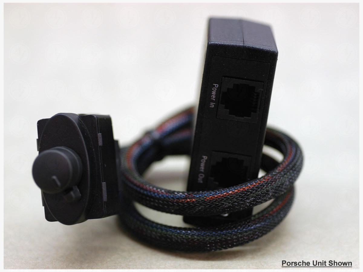
The black wire is ground and the red is for power. Note there is an-line fuse on the red wire.
You will need to cut the red wire between the in-line fuse and the connector that is insterted into the LE-30 controller. Make sure you leave enough wire (at least 4-6 inches) still attached to the plug. Also make sure you have at least 4-6 inches of wire on either side of the in-line fuse.
The purpose of this step is that you want the in-line fuse as close to the power source as possible. You also want it located where it?s easy to access in case it ever needs replacement.
VERY IMPORTANT: be sure to note which end is which on the fuse. You should make sure that you identify the end which was going to the plug for the LE-30 controller versus the end coming from the power source. You will need to know which is which in a few minutes.
Remove the insulation from all wire ends and set aside the red wire with the in-line fuse.
Twist together your power wire that you just ran from the trunk with the red wire attached to the plug. Take one of your wire nuts and secure the connection. Wrap electrical tape around the wire nut (at the base) to be sure everything stays tight.
Now do the same for the black ground wire. Take the other wire you ran from the trunk and a wire nut and secure the connection. Wrap electrical tape around the wire nut (at the base) to be sure everything stays tight.
14. Finding Power
Up until now the worst you should have been able to do was to break some plastic thingee which could easily be replaced. Now you need to really start paying attention. Tapping into electrical power in an inappropriate location on a highly computerized vehicle 12V system is asking for trouble. What fun!
Insert your car key and move the ignition to position 2.
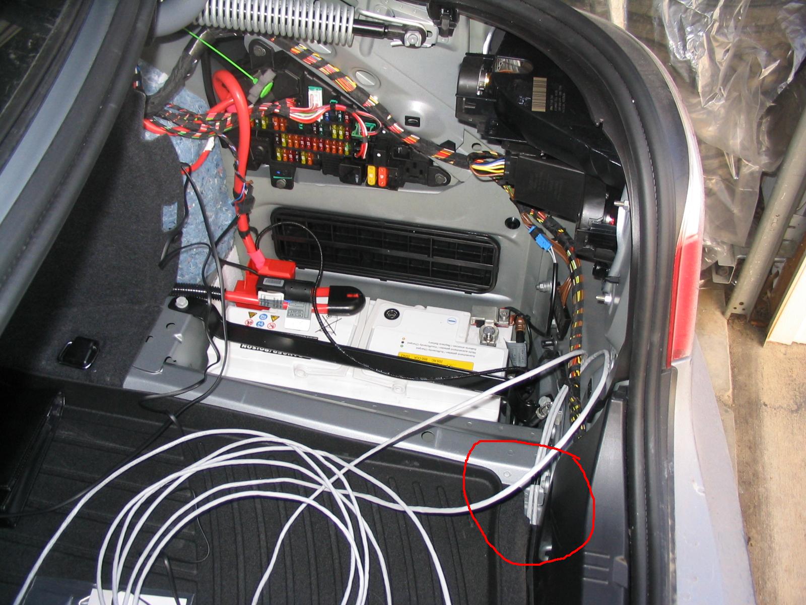
Go to the rear of the vehicle with your voltage tester in hand, make sure you ground the voltage tester! (see step 16 below for tips on where to find ground)
Methodically test the spare circuits in the fuse box [making sure you are using a proper ground while testing - did I mention that?
], and check to see which (if any) circuits light up your voltage testing device.You can identify the non-used but live and available fuse locations by the presence of spade plugs inside the fuse box, but for which no fuse is inserted.
Mark these circuits - mentally or otherwise. In my case they all lit up!
Remove the igntion key. You should now be ready to choose an appropriate connection in the rear fuse box. Go back and start testing again. Make sure your tester is grounded!!
With the ignition OFF and the car key REMOVED from the ignition, take your voltage tester and check the power status of each circuit that you just found was live when the ignition was in position 2. Look for the ones that now DO NOT light up.
You want to find one or more spades that are available but which are NOT registering any voltage with the car's ignition key removed.
Don't hook up anything back here yet, you just want to identify where you will draw power.
Note: also pay attention to which spade (top or bottom) is providing power.

15. Hook up the Ground Wire
First a word about grounding. BMW's (at least late model BMW's) almost always use a solid brown wire as a ground wire. Look around near the rear fuse box and you should find ample sources of a ground connection.
As of this writing, all MY04 and MY05 5-series cars all use solid brown wires for ground.
There is also a set of ground wires in the rear seat side bolster that you were working on earlier, but I do not recommend wiring from there. It is too difficult to access if you are trying to troubleshoot an electrical problem later, which could be the result of a loose ground wire.
Stick to the rear fuse panel area.
Secure the ground wire to either one of the ground wire wiring harnesses (bunch of brown wires) or (prefably) directly to a bolt where one of these wiring harnesses is attached.
Here's an example of what they look like:

16. Wire the Spade
Still at the rear of the vehicle, you need to attach a spade plug to your power wire. You will ultimately insert the spade into your chosen fuse circuit (but not yet) to draw power. You actually don't have to use a spade, but IMO it's the best route.
Now here is where we will revisit the short red wire with the in-line fuse attached to it.
VERY IMPORTANT: Make sure you attach the spade to the correct end of the red wire. Hopefully you labeled them earlier.

If you don't have a spade plug, you can buy one at Radio Shack (or wherever).
Crimp the spade onto the appropriate end of the red wire with the in-line fuse attached to it.
Twist together the other end of the red wire with your power wire run from the front of the car. Take one of your wire nuts and secure the connection. Wrap electrical tape around the wire nut (at the base) to be sure everything stays tight.
17. Final hook-ups
Go back up front and plug your power cables into the LE-30 controller, along with the piezo speaker. Don't worry about the LED yet as that is another mini-project in and of itself.
Plug in the power switch and for now let it hang over the center console or on the floor.
Secure the speaker, excess wiring, and the control unit as you see fit up under the steering column.
Plug in your LE-30 transponder(s) - even if they are not mounted yet - we just want to test the electrical connections.
MAKE SURE THE IGNITION KEY IS REMOVED and go back to the rear of the car. Make sure your ground wire is connected appropriately and then insert your spade plug into your chosen fuse circuit.
Tie up your excess wires and tuck them away somewhere unobtrusive and where they will not interfere with any other wiring. Also make sure you can close the trunk without the mechanism interfering with your wires.
18. It's Alive!
Go back to the front of the car and insert your car key. Move the ignition to ACC or position 2.
Flip the LE-30's power switch and you should hear a beep for each transponder connected.
If you do not get one or more beeps then try the following:
- Remove your car key and check all wiring connections.
- Make sure your connections to the LE-30 controller are in the right position.
- Check to be sure the spade plug did not fall out in the rear fuse panel.
- Remove the spade plug from the fuse panel before you try any of the following:
- Remove your tape and wire nuts and verify the wires are touching. Get your 12 volt tester out. Test the circuit again.
- Use your 12 volt tester and check the ground that you chose.
- If you wired your ground by shoving the ground wire into one of the wiring harnesses, pull it out, strip some more insulation off the end of it and try wiring it to one of the bolts that holds down the wiring harness.

 03-21-2005, 07:07 AM
#23
Contributors
Thread Starter
Join Date: Mar 2005
Location: U.S. of A.
Posts: 170
Likes: 0
Received 0 Likes
on
0 Posts
My Ride: 2005 545, Titanium Gray II, 6 Spd, CWP, Sat, LPP Laser Defense, V1 (hard-wired), iPod, 38% ceramic tint, CDV delete, H&R Street Performance Coil Overs, Forced Air Induction, DriveData Pro Camera System (4 cams), M5 Front Bumper
Originally Posted by alohalc' date='Mar 20 2005, 08:13 PM
holy cow !? road runner, do you work for bmw's service dept  ?
?
!? road runner, do you work for bmw's service dept ?[snapback]104244[/snapback]
He convinced me that this was a do-able DIY project that I could handle and gave me a lot of useful tips on what to do, what not to do.
It beats paying $1500 for an Escort SRX installed.
03-21-2005, 07:10 AM
#24
Contributors
Thread Starter
Join Date: Mar 2005
Location: U.S. of A.
Posts: 170
Likes: 0
Received 0 Likes
on
0 Posts
My Ride: 2005 545, Titanium Gray II, 6 Spd, CWP, Sat, LPP Laser Defense, V1 (hard-wired), iPod, 38% ceramic tint, CDV delete, H&R Street Performance Coil Overs, Forced Air Induction, DriveData Pro Camera System (4 cams), M5 Front Bumper
BTW, last night I discovered that my plan to install the LE-30 power switch in the driver seat controls, using a Radio Shack rocker switch that could pass for OEM was a very BAD IDEA.
Let me just advise everyone not to take those darn things apart. It's almost impossible to get back together.
I am looking at a $160 lesson as I ordered a new one this morning. :'(
Where have other members installed their power switch? I'm especially interested in anyone who has used a switch other than the one which comes with the LE-30 kit.
03-21-2005, 07:39 AM
#25
Contributors

Join Date: May 2004
Location: Colorado, USA
Posts: 822
Likes: 0
Received 0 Likes
on
0 Posts
I have a feeling that you are one of the first, or nobody has spoken up.
I was thinking about putting it down near the opening for the OBD/hood release.
I also thought about triing to get the BMW button that would go in space by the foglight. I will try and find a picture, as I have only seen them on the euro cars.
I was thinking about putting it down near the opening for the OBD/hood release.
I also thought about triing to get the BMW button that would go in space by the foglight. I will try and find a picture, as I have only seen them on the euro cars.
03-21-2005, 07:45 AM
#26
Super Moderator
Join Date: Mar 2004
Location: Pittsburgh, PA USA
Posts: 17,310
Likes: 0
Received 2 Likes
on
2 Posts
My Ride: G30 M550i
Model Year: 2018
Originally Posted by CRRobert' date='Mar 21 2005, 11:39 AM
I also thought about triing to get the BMW button that would go in space by the foglight.? I will try and find a picture, as I have only seen them on the euro cars.
[snapback]104559[/snapback]
03-21-2005, 07:46 AM
#27
Contributors
Join Date: May 2004
Location: Colorado, USA
Posts: 822
Likes: 0
Received 0 Likes
on
0 Posts
Found a pic, of course it is Iceman's car, but it is were their Hud button is, which I would think is an on off switch(versus our location for the hud, which is their rear fog).
03-21-2005, 08:00 AM
#28
Super Moderator
Join Date: Mar 2004
Location: Pittsburgh, PA USA
Posts: 17,310
Likes: 0
Received 2 Likes
on
2 Posts
My Ride: G30 M550i
Model Year: 2018
I'm not sure you're following me. Any switch can be an on/off switch but there are different types of switches.
Some switches are "push on, push off" type that, when you push them, will stay down halfway (to keep the circuit closed) and when you push them again, will pop back up (to open the circuit.)
Another type of switch is the "momentary" type which, when pressed, closes the circuit momentarily before returning back (not stopping halfway down) to open the circuit. These are the types of switches that are used near the headlight switch. BMW's software deals with keeping the device on or off, it just looks for the signal from the momentary switch to toggle the device's state from on to off.
I'm worried that the jammer you're installing needs a switch that maintains closure on the circuit to keep it jamming...
03-21-2005, 08:07 AM
#30
Contributors
Thread Starter
Join Date: Mar 2005
Location: U.S. of A.
Posts: 170
Likes: 0
Received 0 Likes
on
0 Posts
My Ride: 2005 545, Titanium Gray II, 6 Spd, CWP, Sat, LPP Laser Defense, V1 (hard-wired), iPod, 38% ceramic tint, CDV delete, H&R Street Performance Coil Overs, Forced Air Induction, DriveData Pro Camera System (4 cams), M5 Front Bumper
Originally Posted by CRRobert' date='Mar 21 2005, 12:46 PM
Found a pic, of course it is Iceman's car, but it is were their Hud button is, which I would think is an on off switch(versus our location for the hud, which is their rear fog).
I've installed my V1 remote audio control behind that panel (need to upload some pics) and I can tell you that it's difficult to find much space behind the headlight switch panel.
The headlight switch assembly (and presumably the space with the HUD switch, tho I would have to look at the inside of the panel again to say for sure) is contained inside a plastic box that bolts to the inside of the dash panel.
Between that and the clips which hold the panel in, there is not much room.
In fact, for my V1 Remote Audio unit, I used a remote remote (so to speak) from AIdesign. It cost me $177 including shipping.
So, to use the HUD switch you would have to hack into the plastic box thingee. I would recommend against that, based on my lesson with the seat controls.

Furthermore, I also suspect that Rudy is right and those switches are most likely momentary, which would not work with the LE-30 (it uses an open/close type switch).
If I could find a suitably small and inconspicuous looking switch, I would consider that location tho (provided I can fit it underneath my V1 audio/power knob).
One other noteworthy item - it is VERY easy to damage the laminated wood panel above the headlight switch dash cover when you pop it out. My car is a lease, so I could care less about the minor damage that I did.
You will need to use a flat head screwdriver to remove the panel. There are 2 slits along the bottom of the plastic panel. Wedge your screwdriver in and SLOWLY see-saw it back and forth (forward to rear) until the panel starts to give from the rest of the dash. There are (I believe) 3 clips that attach it.... one on the left and 2 on the right. The panel will tend to come off suddenly when the clips give.
I don't have any good advice on how to avoid damaging the laminated wood dash panels. As I said, it's very difficult not to. I know that many BMW service dept techs have the same problem until they get used to working with the E60 interior.