
Laser Jammer Install Locations
 03-17-2005, 09:07 PM
#11
Members

Join Date: Feb 2005
Location: So. California
Posts: 237
Likes: 0
Received 0 Likes
on
0 Posts
My Ride: '05 545 Sport Week 9
Originally Posted by Road Runner' date='Mar 17 2005, 09:00 PM
Ok, will do.? I need to resurrect the hard drive on my network that contains the pics (the file server had a bad hair day last week).?
I should be able to post some info over the weekend.
I should be able to post some info over the weekend.
[snapback]103132[/snapback]
 03-18-2005, 08:43 AM
#12
Contributors

Join Date: May 2004
Location: Colorado, USA
Posts: 822
Likes: 0
Received 0 Likes
on
0 Posts
03-19-2005, 03:15 PM
#13
Contributors
Thread Starter

Join Date: Mar 2005
Location: U.S. of A.
Posts: 170
Likes: 0
Received 0 Likes
on
0 Posts
My Ride: 2005 545, Titanium Gray II, 6 Spd, CWP, Sat, LPP Laser Defense, V1 (hard-wired), iPod, 38% ceramic tint, CDV delete, H&R Street Performance Coil Overs, Forced Air Induction, DriveData Pro Camera System (4 cams), M5 Front Bumper
Ok... here are the written instructions. I'll post pics later this weekend when I can.
Also, if anyone would like detailed instructions on how I installed both a V1 and dual Lidatek LE-30's, let me know and I can either e-mail you or post them on the board.
--------
Rear Parcel Shelf - Access, V1 Installation
Tools/Parts You Will Need
- Flat blade screw driver
- Philips head screw driver (#2)
- T40 Torx screw driver or ratchet bit
- Small plastic bags to keep parts in temporarily (sandwich bag size works well)
- A few zip ties
- Upholstery puller (available at most automotive hardware stores)
0. Remove trunk mat
Lift trunk mat covering spare tire. Pull the handle firmly toward you. The rubber it is attached to will stretch, allowing you to wrap the curved handle up over the lip on the bottom of the raised trunk lid.
Now carefully pull up those strange looking tongue-in-groove Styrofoam pads. Put them in a safe place where you will not accidentally tear them up while working.
1. Remove trunk panels
I suggest removing both passenger side and driver side. You'll have to decide for yourself which side to run the wires. Personally, I chose the drivers side because I planned to install a remote audio and concealed display unit up front within reach/sight of the driving position. I also wanted to run a wire long enough that if I ever opted for Beast Power's V1 / Lidatek integrated rear mirror that I'd have a long enough cable run. There is tons of room in the drivers side rear corner to stuff some extra "just in case" wiring.
2. Removing the Rear Seats - Part I
Easiest step. First you want to remove the back seat cushion (the part you sit on). Just pull up from the front part of the seat cushion. It should easily pop up. Reach up underneath the front lip of the bottom seat cushion, feel your way back about 2 or 3 inches from the front edge and about 6-9 inches or so from the drivers/passenger edge. Get a good grip and pull up firmly. The seat should easily pop up. If not then feel around for the latch as you are doing something wrong if this is not easier than it looks.
3. Removing the Rear Seats ? Part II
If you have fold-down rear seats, fold them down. If you don't have fold down seats then it's going to take a bit more work and sorry but I can't fully help you as my car does have the fold down seats!
I believe that if you have the fixed rear seat back then next you'll need to remove six (?) bolts. This will allow you to remove the seat back (I think... have not been able to verify... someone please post who knows).
4. Removing the Rear Seats ? Part III
Remove the side bolsters to the outer rear seating positions (one on each side of the backseat). To do this pull the top portion of each side bolster toward you. Give them a good tug, pulling them forward toward the front of the car. They should pop out with some slight effort. Then lift upward and forward at the same time. The lower portion of each side bolster is secured by a metal "tooth" about an inch wide that is inserted into a groove. You may need to tug upward while pulling it out.
Now, do yourself a favor (hint: timesaver when you put this back together) and extract the plug for the top portion of the seat bolster from within the seat frame. I can't remember if you need to push the tab inside of it down or pull it up... I think you push it down, but it only moves one way (sorry!... doh.. my old age of 37 and my memory is already failing).
Once you wiggle this out, snap it onto the back of the seat bolster. The back of the side bolster has a short piece at the top that looks like a black tube about 2 inches wide. That is where you shove this clip. Make sure you point it in the correct direction. This will allow you to very easily snap the bolster back into the seat frame when you re-install them once you've run your wires.
[I must have spent 15 minutes the first time I put my seat back together before following this procedure, just trying to get the seat bolster back in the damn clip. Taking the clip out and sticking it on the end of the bolster is MUCH easier. ]
]
At this point you should see a bunch of wires bound together bundled along both the drivers and passenger sides of the car, which are normally hidden beneath these side seat bolster things. This is how you will run your wires from the trunk are to the floor side sills. Look down and you'll see that there is a big gap in the floor sill on either side. This is your ticket when you get to the wiring part.
5. Loosen the felt lined covers
On either side of the rear seat there is a felt lined cover that extends from behind the rear seat and rests against the side bolster and goes back inside the trunk area. These covers are a pretty good size, maybe 2 or 2 1/2 feet long. You cannot fully access these until after removing the side bolsters of the rear seat back.
There is a clip inside the trunk area that attaches to a metal bracket. Remove the plastic nail / insert / plastic screw doo-hickey and pop out the screw for each one. This will give you more flexibility in running the wires in a few minutes.
Now, get in the back seat area and do the same for the clips on the other side. There is one near the top of the seat back, next to the side bolsters.
Now we are done with the prep for running the wires. But we still don't have access to the rear shelf. Almost there. You don't want to start running your wires until you get access beneath the shelf, because you will have some decisons to make on exactly where you to mount the V1.
6. Remove covering over the edge of the rear shelf
There are 5 plastic nails along the top rail of this thing. Again I'm assuming you've got the fold down seats (if you don't then this step may not apply - I don't know).
Use a flat head screwdriver to loosen each screw by carefully prying it up. You should then be able to pull them out with your fingers. Pry out the jacket that each screw sits in and set aside all screws and jackets.
Now you have access to a cover that holds the rear shelf in place from the front side. Pull the cover off. It should slide off toward you. You may need to jiggle it around to loosen it up, but it should not be too difficult.
7. Remove the ISOFIX / LATCH bolts
Note: You'll need a T40 torx ("star") screwdriver or bit. I suggest a ratchet bit as most screwdrivers will not fit under the narrow rake of the rear window. You can purchase one at most auto hardware stores.
These things are another piece of cake. Once you get the screws loosened up they will lift right out, fully intact.
8. Lift up or pull out the rear shelf
Personally, I do not recommend removing the rear shelf at this point. I recommend lifting up the shelf and holding it up while you position your V1.
IMHO removing the rear shelf is just not necessary and it's a big PITA to get the damn thing back in properly. There are 2-3 side panels that are intertwined with the outer rear seat belt assemblies. These must all be removed in order to fully remove the rear parcel shelf. Aside from that PITA, getting the shelf back in is another PITA. Get the point? I strongly recommend just lifting up the shelf. There is plenty of play to allow you to work mounting the V1 and running / concealing wires.
All you need to do is lift the shelf up at any point that you would like. It is very pliable (don't get carried away... but you get the picture).
Now look around and start thinking about where you'd like your V1 positioned and how you will prevent it from moving around in there. Note: Before I buttoned up the install, I did some unscientific testing while I had my rear shelf apart. I placed the V1 where I thought it would work best for me and then took off for some spirited driving and high speed donuts in my neighborhood. I'm sure my neighbors now think I'm quite strange, but who cares. BTW, its amazing how much sound proofing of the exhaust noise that back seat provides.
After "testing" your mounting position you can move on to the wiring.
A few suggestions on positioning your V1 and how to keep it where you want it!
There are two challenges with the rear parcel shelf install. 1) how do you keep the V1 from moving around and pointing in the wrong direction, when you can't see it to know if it's pointed correctly or not? And 2) where exactly to mount it under the shelf.
For me, issue # 2 was easier to identify. I have a child seat in the center seating position, so the (ideal) position behind the center head rest was out. Through much back and forth between the back seat and front of the car, I determined there was a sufficient gap measured horizontally between the edge of the baby seat and the front passenger head rest where the V1 could "see" between them. So, this became my choice of location underneath the rear shelf.
Another concern I had - even if I moved the baby seat to an outboard position, there is a significant amount of metal in the top of the center seating position (above the ski bag) and to some extent within the top portion of the center back rest. It was enough to make me think that it could interfere with the V1's performance, though I honestly doubt that it would be significant. Bottom line for me was that my kid's safety (center of car) is more important to me than the V1 mounting location.
Regarding issue # 1 above - how to keep it in place - I came up with two ideas. One (the method I used) is to take the foam which holds the V1 in its box that it comes with from Valentine. Cut out the foam in front of and behind the V1 just to be sure you are not reducing its range any more than necessary. The remaining foam beaneath, above, and on the sides should be sufficient.
You'll notice there is not much room (vertically) inside the rear shelf area to begin with. I found that the height was just about perfectly matched to that of the V1. Having the V1 inside the foam meant that the rear shelf was essentially pressing it into place. This is especially true after you reinstall the ISOFIX brackets.
The other option I thought of was to fabricate a wooden box to hold the V1. Again I'd suggest using the foam that the V1 ships in from Valentine (or something similar) to hold the V1 comfortably in place inside your box.
The advantage to the wood box method is that you can be certain of holding it in place. Once you decide on placement of the box, there are seveal holes accessable from inside the trunk which could be used to drill a screw up into your wood box.
Good luck and please let me know of any errata or suggested improvements!
Also, if anyone would like detailed instructions on how I installed both a V1 and dual Lidatek LE-30's, let me know and I can either e-mail you or post them on the board.
--------
Rear Parcel Shelf - Access, V1 Installation
Tools/Parts You Will Need
- Flat blade screw driver
- Philips head screw driver (#2)
- T40 Torx screw driver or ratchet bit
- Small plastic bags to keep parts in temporarily (sandwich bag size works well)
- A few zip ties
- Upholstery puller (available at most automotive hardware stores)
0. Remove trunk mat
Lift trunk mat covering spare tire. Pull the handle firmly toward you. The rubber it is attached to will stretch, allowing you to wrap the curved handle up over the lip on the bottom of the raised trunk lid.
Now carefully pull up those strange looking tongue-in-groove Styrofoam pads. Put them in a safe place where you will not accidentally tear them up while working.
1. Remove trunk panels
I suggest removing both passenger side and driver side. You'll have to decide for yourself which side to run the wires. Personally, I chose the drivers side because I planned to install a remote audio and concealed display unit up front within reach/sight of the driving position. I also wanted to run a wire long enough that if I ever opted for Beast Power's V1 / Lidatek integrated rear mirror that I'd have a long enough cable run. There is tons of room in the drivers side rear corner to stuff some extra "just in case" wiring.
2. Removing the Rear Seats - Part I
Easiest step. First you want to remove the back seat cushion (the part you sit on). Just pull up from the front part of the seat cushion. It should easily pop up. Reach up underneath the front lip of the bottom seat cushion, feel your way back about 2 or 3 inches from the front edge and about 6-9 inches or so from the drivers/passenger edge. Get a good grip and pull up firmly. The seat should easily pop up. If not then feel around for the latch as you are doing something wrong if this is not easier than it looks.
3. Removing the Rear Seats ? Part II
If you have fold-down rear seats, fold them down. If you don't have fold down seats then it's going to take a bit more work and sorry but I can't fully help you as my car does have the fold down seats!
I believe that if you have the fixed rear seat back then next you'll need to remove six (?) bolts. This will allow you to remove the seat back (I think... have not been able to verify... someone please post who knows).
4. Removing the Rear Seats ? Part III
Remove the side bolsters to the outer rear seating positions (one on each side of the backseat). To do this pull the top portion of each side bolster toward you. Give them a good tug, pulling them forward toward the front of the car. They should pop out with some slight effort. Then lift upward and forward at the same time. The lower portion of each side bolster is secured by a metal "tooth" about an inch wide that is inserted into a groove. You may need to tug upward while pulling it out.
Now, do yourself a favor (hint: timesaver when you put this back together) and extract the plug for the top portion of the seat bolster from within the seat frame. I can't remember if you need to push the tab inside of it down or pull it up... I think you push it down, but it only moves one way (sorry!... doh.. my old age of 37 and my memory is already failing).
Once you wiggle this out, snap it onto the back of the seat bolster. The back of the side bolster has a short piece at the top that looks like a black tube about 2 inches wide. That is where you shove this clip. Make sure you point it in the correct direction. This will allow you to very easily snap the bolster back into the seat frame when you re-install them once you've run your wires.
[I must have spent 15 minutes the first time I put my seat back together before following this procedure, just trying to get the seat bolster back in the damn clip. Taking the clip out and sticking it on the end of the bolster is MUCH easier.
]At this point you should see a bunch of wires bound together bundled along both the drivers and passenger sides of the car, which are normally hidden beneath these side seat bolster things. This is how you will run your wires from the trunk are to the floor side sills. Look down and you'll see that there is a big gap in the floor sill on either side. This is your ticket when you get to the wiring part.
5. Loosen the felt lined covers
On either side of the rear seat there is a felt lined cover that extends from behind the rear seat and rests against the side bolster and goes back inside the trunk area. These covers are a pretty good size, maybe 2 or 2 1/2 feet long. You cannot fully access these until after removing the side bolsters of the rear seat back.
There is a clip inside the trunk area that attaches to a metal bracket. Remove the plastic nail / insert / plastic screw doo-hickey and pop out the screw for each one. This will give you more flexibility in running the wires in a few minutes.
Now, get in the back seat area and do the same for the clips on the other side. There is one near the top of the seat back, next to the side bolsters.
Now we are done with the prep for running the wires. But we still don't have access to the rear shelf. Almost there. You don't want to start running your wires until you get access beneath the shelf, because you will have some decisons to make on exactly where you to mount the V1.
6. Remove covering over the edge of the rear shelf
There are 5 plastic nails along the top rail of this thing. Again I'm assuming you've got the fold down seats (if you don't then this step may not apply - I don't know).
Use a flat head screwdriver to loosen each screw by carefully prying it up. You should then be able to pull them out with your fingers. Pry out the jacket that each screw sits in and set aside all screws and jackets.
Now you have access to a cover that holds the rear shelf in place from the front side. Pull the cover off. It should slide off toward you. You may need to jiggle it around to loosen it up, but it should not be too difficult.
7. Remove the ISOFIX / LATCH bolts
Note: You'll need a T40 torx ("star") screwdriver or bit. I suggest a ratchet bit as most screwdrivers will not fit under the narrow rake of the rear window. You can purchase one at most auto hardware stores.
These things are another piece of cake. Once you get the screws loosened up they will lift right out, fully intact.
8. Lift up or pull out the rear shelf
Personally, I do not recommend removing the rear shelf at this point. I recommend lifting up the shelf and holding it up while you position your V1.
IMHO removing the rear shelf is just not necessary and it's a big PITA to get the damn thing back in properly. There are 2-3 side panels that are intertwined with the outer rear seat belt assemblies. These must all be removed in order to fully remove the rear parcel shelf. Aside from that PITA, getting the shelf back in is another PITA. Get the point? I strongly recommend just lifting up the shelf. There is plenty of play to allow you to work mounting the V1 and running / concealing wires.
All you need to do is lift the shelf up at any point that you would like. It is very pliable (don't get carried away... but you get the picture).
Now look around and start thinking about where you'd like your V1 positioned and how you will prevent it from moving around in there. Note: Before I buttoned up the install, I did some unscientific testing while I had my rear shelf apart. I placed the V1 where I thought it would work best for me and then took off for some spirited driving and high speed donuts in my neighborhood. I'm sure my neighbors now think I'm quite strange, but who cares. BTW, its amazing how much sound proofing of the exhaust noise that back seat provides.
After "testing" your mounting position you can move on to the wiring.
A few suggestions on positioning your V1 and how to keep it where you want it!
There are two challenges with the rear parcel shelf install. 1) how do you keep the V1 from moving around and pointing in the wrong direction, when you can't see it to know if it's pointed correctly or not? And 2) where exactly to mount it under the shelf.
For me, issue # 2 was easier to identify. I have a child seat in the center seating position, so the (ideal) position behind the center head rest was out. Through much back and forth between the back seat and front of the car, I determined there was a sufficient gap measured horizontally between the edge of the baby seat and the front passenger head rest where the V1 could "see" between them. So, this became my choice of location underneath the rear shelf.
Another concern I had - even if I moved the baby seat to an outboard position, there is a significant amount of metal in the top of the center seating position (above the ski bag) and to some extent within the top portion of the center back rest. It was enough to make me think that it could interfere with the V1's performance, though I honestly doubt that it would be significant. Bottom line for me was that my kid's safety (center of car) is more important to me than the V1 mounting location.
Regarding issue # 1 above - how to keep it in place - I came up with two ideas. One (the method I used) is to take the foam which holds the V1 in its box that it comes with from Valentine. Cut out the foam in front of and behind the V1 just to be sure you are not reducing its range any more than necessary. The remaining foam beaneath, above, and on the sides should be sufficient.
You'll notice there is not much room (vertically) inside the rear shelf area to begin with. I found that the height was just about perfectly matched to that of the V1. Having the V1 inside the foam meant that the rear shelf was essentially pressing it into place. This is especially true after you reinstall the ISOFIX brackets.
The other option I thought of was to fabricate a wooden box to hold the V1. Again I'd suggest using the foam that the V1 ships in from Valentine (or something similar) to hold the V1 comfortably in place inside your box.
The advantage to the wood box method is that you can be certain of holding it in place. Once you decide on placement of the box, there are seveal holes accessable from inside the trunk which could be used to drill a screw up into your wood box.
Good luck and please let me know of any errata or suggested improvements!
03-19-2005, 03:17 PM
#14
Contributors
Thread Starter
Join Date: Mar 2005
Location: U.S. of A.
Posts: 170
Likes: 0
Received 0 Likes
on
0 Posts
My Ride: 2005 545, Titanium Gray II, 6 Spd, CWP, Sat, LPP Laser Defense, V1 (hard-wired), iPod, 38% ceramic tint, CDV delete, H&R Street Performance Coil Overs, Forced Air Induction, DriveData Pro Camera System (4 cams), M5 Front Bumper
Doh... edit to the Tools Required that I listed above.
You really only need the T40 Torx ("Star") ratchet bit or screwdriver and a flat head screw driver.
You really only need the T40 Torx ("Star") ratchet bit or screwdriver and a flat head screw driver.
03-19-2005, 04:25 PM
#15
Contributors
Join Date: May 2004
Location: Colorado, USA
Posts: 822
Likes: 0
Received 0 Likes
on
0 Posts
As much information on the Lidatek install as possible, wire routing etc. Please.
I was taking pictures for research of my install.
Pics would be helpfull, and sure that all board members would appreciate. May want to start a new thread in DIY to document your install.
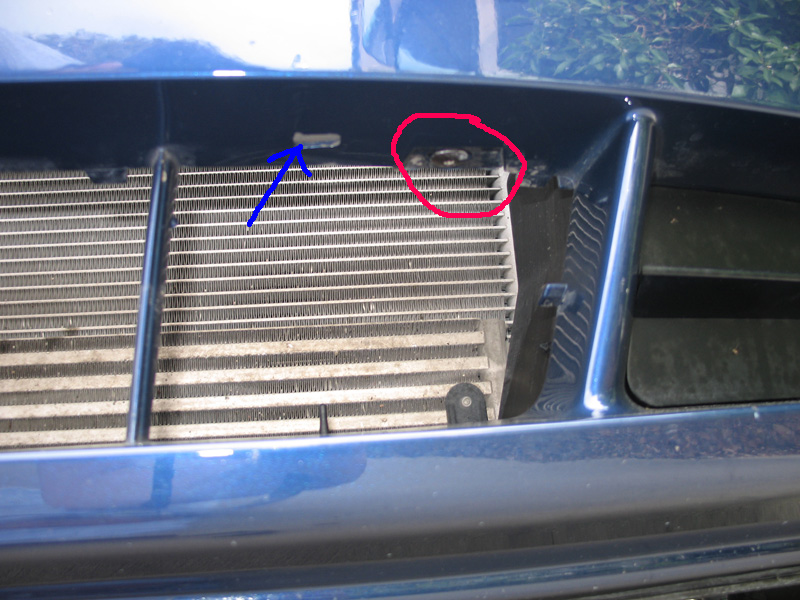
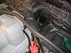
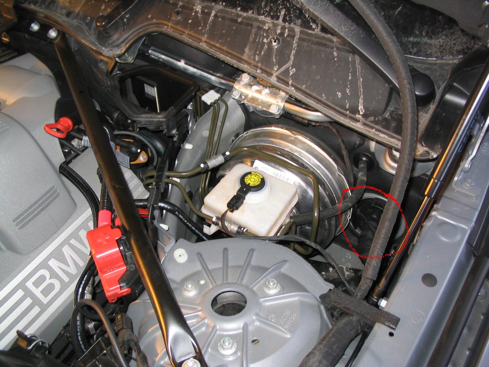
This is were I was planning on installing. The hole, blue arrow, is for the license plate frame, and was looking to attach the hardware to the bolt, red circle.

I was taking pictures for research of my install.
Pics would be helpfull, and sure that all board members would appreciate. May want to start a new thread in DIY to document your install.
This is were I was planning on installing. The hole, blue arrow, is for the license plate frame, and was looking to attach the hardware to the bolt, red circle.
 03-19-2005, 05:41 PM
#16
Contributors
Thread Starter
Join Date: Mar 2005
Location: U.S. of A.
Posts: 170
Likes: 0
Received 0 Likes
on
0 Posts
My Ride: 2005 545, Titanium Gray II, 6 Spd, CWP, Sat, LPP Laser Defense, V1 (hard-wired), iPod, 38% ceramic tint, CDV delete, H&R Street Performance Coil Overs, Forced Air Induction, DriveData Pro Camera System (4 cams), M5 Front Bumper
Originally Posted by CRRobert' date='Mar 19 2005, 09:25 PM
As much information on the Lidatek install as possible, wire routing etc. Please.
I was taking pictures for research of my install.?
Pics would be helpfull, and sure that all board members would appreciate.? May want to start a new thread in DIY to document your install.
This is were I was planning on installing.? The hole, blue arrow, is for the license plate frame, and was looking to attach the hardware to the bolt, red circle.
Attachment 5901
[snapback]103921[/snapback]
But while we're on the subject here, I'm planning to install dual LE-30's in the exact same spot you outlined in your pic.
My only issue has been placing each LE-30 where I want it using the install kit supplied from Lidatek.
The best method I've come up with so far entails using a 4" mounting rail and the square shaped bracket, where the end of the opening with the shortest width is facing forward. This means the LE-30 will sit along the length of the bracket rather than sideways as it is pictured in the LE-30 install manual.
Reason for this method is that I don't want the bracket to be very visible from in front of the car if possible. I found that turning the bracket sideways (as in the manual) causes the bracket to stick out sideways due to the bolt in that holds the two pieces of the bracket together.
No matter how I've tried it though, it is difficult to get the mount where I want it - as close to the vertical beam in the bumper as possible (the beam separating the front air dam to the radiator and the front air dams that route to the brakes).
Another issue that may interest you is that in either configuration the screw which would be used to mount the 4" mounting rail is barely long enough if the 4" mounting rail is bent slightly. If not bent then the screw is too short to ensure that it remains secured (I had one fall out while I was playing around with the position of all the parts).
I'm off to Home Depot or Lowe's tomorrow to try and find a longer version that fits.
Also note the head on the OEM screw is a T-25 (Torx).
 03-19-2005, 05:54 PM
#17
Contributors
Join Date: May 2004
Location: Colorado, USA
Posts: 822
Likes: 0
Received 0 Likes
on
0 Posts
roadrunner,
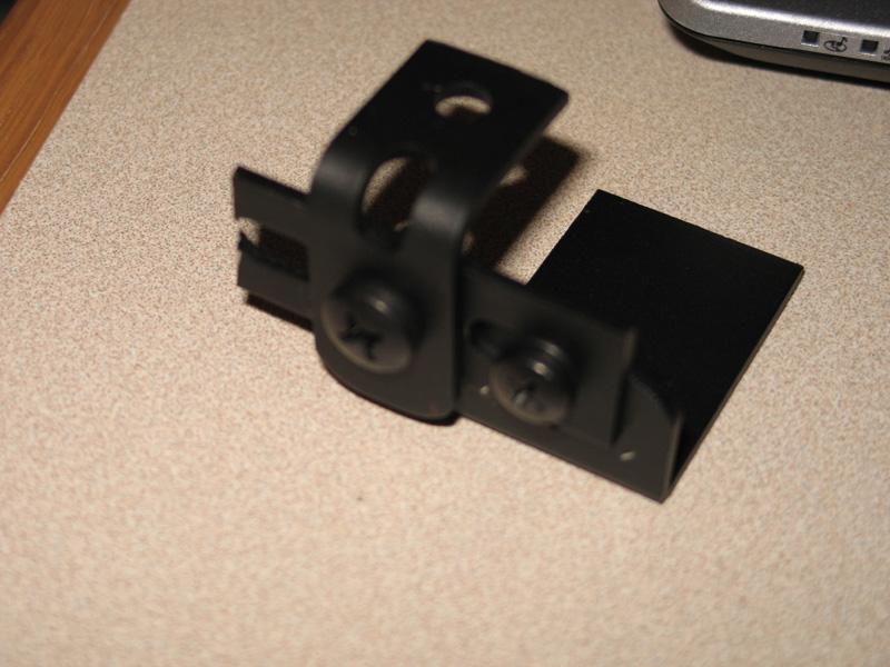
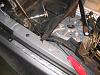
I was just playing around with the harware, and came up with the following. I bent one of the smaller peices, and then cut it. It is a little bulky, but I think keeps it close to the pillar like you describe, but also allows to keep forward so it is not too recessed.
Off to pick up dinner.
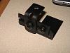
I was just playing around with the harware, and came up with the following. I bent one of the smaller peices, and then cut it. It is a little bulky, but I think keeps it close to the pillar like you describe, but also allows to keep forward so it is not too recessed.
Off to pick up dinner.
 03-19-2005, 06:13 PM
#18
Contributors
Thread Starter
Join Date: Mar 2005
Location: U.S. of A.
Posts: 170
Likes: 0
Received 0 Likes
on
0 Posts
My Ride: 2005 545, Titanium Gray II, 6 Spd, CWP, Sat, LPP Laser Defense, V1 (hard-wired), iPod, 38% ceramic tint, CDV delete, H&R Street Performance Coil Overs, Forced Air Induction, DriveData Pro Camera System (4 cams), M5 Front Bumper
Originally Posted by CRRobert' date='Mar 19 2005, 10:54 PM
roadrunner,
I was just playing around with the harware, and came up with the following.? I bent one of the smaller peices, and then cut it.? It is a little bulky, but I think keeps it close to the pillar like you describe, but also allows to keep forward so it is not too recessed.
I was just playing around with the harware, and came up with the following.? I bent one of the smaller peices, and then cut it.? It is a little bulky, but I think keeps it close to the pillar like you describe, but also allows to keep forward so it is not too recessed.
[snapback]103935[/snapback]
Nice!!
I'll try that out tomorrow!
RR
 03-19-2005, 06:56 PM
#19
Contributors
Thread Starter
Join Date: Mar 2005
Location: U.S. of A.
Posts: 170
Likes: 0
Received 0 Likes
on
0 Posts
My Ride: 2005 545, Titanium Gray II, 6 Spd, CWP, Sat, LPP Laser Defense, V1 (hard-wired), iPod, 38% ceramic tint, CDV delete, H&R Street Performance Coil Overs, Forced Air Induction, DriveData Pro Camera System (4 cams), M5 Front Bumper
Regarding the wiring.... I found the wiring to be the easy part (relatively speaking). The toughest part IMHO is choosing the location of the transponders and figuring out how to put them there.
At any rate, here's how I've handled the wiring and some tips for others so as not to repeat my mistakes.
I need to find the time to post my entire install (with pics) of my V1 rear shelf and LE-30 installs, but this guide should give you info on the toughest part of the wiring job.
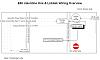
Wiring Diagram & Fuse Panels
First off, I ran wiring for my rear shelf V1 install at the same time. So the diagram I've attached below shows the wiring route for both installs. I'll post more info on the V1 section under the separate thread I created a few mins. ago.
Second, there are two fuse panels in the E60 - one in front behind the glove box and one in rear above the battery (just in front of the rear passenger tail lights).
I recommend wiring from the rear fuse panel. On my car there was only ONE - yes ONE - unused circuit that I could tap into which was an ACC switched circuit (only comes on when ignition key is in position 2). All the other unused circuits were Constant On (always has power).
Furthermore, the rear panel is much easier to gain full access to. However, if anyone would like instructions on accessing the front panel, including how to handle the glove compartment, let me know.
Power
The only downside to going with the rear panel is that you should cut the red power wire going to the LE-30 controller. Reason being that you want the in-line fuse as close to the fuse panel as possible. So, if you get power from the rear of the car then you should move the in-line fuse to the same compartment where you're drawing power. This makes any future troubleshooting much easier and also means you are less likely have any nasty electrical problems - bottom line is it's the safer and smarter approach.
Ground
Well, obviously you want to run the ground from around the same area as the power wire.... Did I mention there were three reasons I chose to use the rear panel and not two?
Finding and gaining access to a ground wire from the front is a major PITA. First off, are you going to go thru the firewall plug (which is on the drivers side - the front fuse panel is on the passenger side of the car). Or are you going to try and figure out what's what in the plastic box that protrudes thru the firewall on the passenger side? Good luck with that one. I never did figure out what all that stuf does, and I decided it was a bad idea to mess with it.
So, it is much easier to run ground to the rear of the car. There are grounding points all over the place (I'm sure there are some in front, I just never found any).
The ground wires on the E60 are solid brown. If you see any solid brown wire, it is a ground.
Best method is to tap into one of the many screws in the trunk cubby areas (just in front of the tail lights) that grounds multiple wires. You can't miss the harnesses.
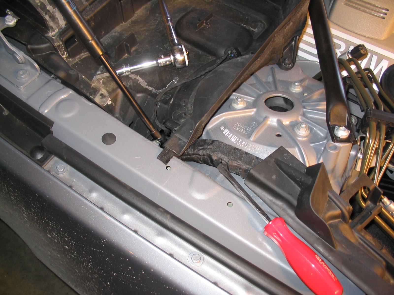
Poking Thru the Firewall
Access thru the firewall is on the drivers side. It's best to do this from the engine side and poke a hole into the passenger compartment.
The access point is covered with a rubber grommet that is at least a couple inches in diameter. There is a nipple in the center which helps facilitate poking through it without making a mess and exposing yourself to H2O leakage problems.
You will need to make about a 1/2 inch or so slit - wide enough to fit the DIN plugs through.
To access this you will need to remove the following parts under the hood:
1. Plastic covers which conceal the windshield wiper motors
2. Passenger cabin air filter assemblies
3. Plastic tray that the cabin air filters sit on
#1: Remove the following:
- Thin horizontal plastic cover, which is covering the covers that you need to remove. This cover slides horizontally (I don't recall which direction) and then pops out.
- Weatherstripping which runs horizontally across the width of the car, just forward of the plastic covers.
- Now you need to unscrew the plastic covers. The drivers side comes out first. You will need a T20 (Torx/Star) screwdriver to remove these.
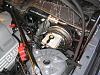
#2: Passenger cabin air filter assemblies
- There are 3 hex bolts. I believe they are 8mm, but I won't swear to it.
- Loosen them about a 1/4 turn. There are tabs underneath that hold each cabin air filter cover down.
- Lift up the air filter cover. Note that the passenger side has a sensor attached to it.
- Set aside the filters and aforementioned sensor.
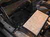
Air Filter Popped Out
Sensor Wire
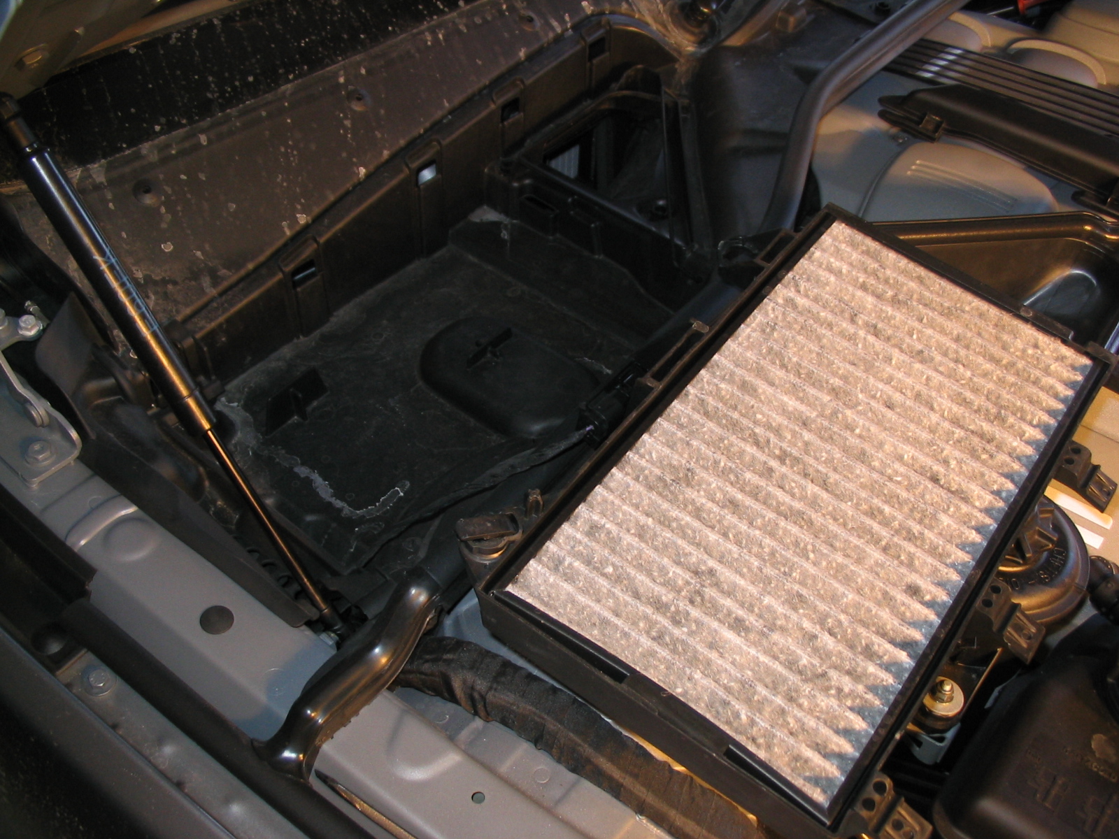
#3: Turn some more hex bolts to get the air filter assemblies out
- Loosen the bolts, lift to remove.
- You only need to get the drivers side out.
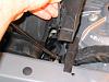
FINALLY!!! You should see this...
Pull Some Wires (Finally)
1. Run a pull wire or fish wire of some sort from the engine bay thru to the passenger compartment.
2. Pull your transponder wires thru, DIN plug end, into the engine compartment.
3. Tuck your wires so they follow the existing wire bundle and the hood opener pull cords. I placed mine more or less beneath the existing wire bundle to be sure the hood would not crunch them when closed.
4. Ideally you should mount the transponders now, or at least choose their location so that you can figure out how much wire you need. Take your leftover wire and feed it back into the passenger compartment. It will be easier to hide it there under the dash.
5. Use some electrical tape or weatherproof sealant of some sort and make sure no moisture can get thru your hole in the firewall.
6. Button everything back up. You're ready to install the transponders and hook up the wiring inside the passenger compartment.
At any rate, here's how I've handled the wiring and some tips for others so as not to repeat my mistakes.
I need to find the time to post my entire install (with pics) of my V1 rear shelf and LE-30 installs, but this guide should give you info on the toughest part of the wiring job.
Wiring Diagram & Fuse Panels
First off, I ran wiring for my rear shelf V1 install at the same time. So the diagram I've attached below shows the wiring route for both installs. I'll post more info on the V1 section under the separate thread I created a few mins. ago.
Second, there are two fuse panels in the E60 - one in front behind the glove box and one in rear above the battery (just in front of the rear passenger tail lights).
I recommend wiring from the rear fuse panel. On my car there was only ONE - yes ONE - unused circuit that I could tap into which was an ACC switched circuit (only comes on when ignition key is in position 2). All the other unused circuits were Constant On (always has power).
Furthermore, the rear panel is much easier to gain full access to. However, if anyone would like instructions on accessing the front panel, including how to handle the glove compartment, let me know.
Power
The only downside to going with the rear panel is that you should cut the red power wire going to the LE-30 controller. Reason being that you want the in-line fuse as close to the fuse panel as possible. So, if you get power from the rear of the car then you should move the in-line fuse to the same compartment where you're drawing power. This makes any future troubleshooting much easier and also means you are less likely have any nasty electrical problems - bottom line is it's the safer and smarter approach.
Ground
Well, obviously you want to run the ground from around the same area as the power wire.... Did I mention there were three reasons I chose to use the rear panel and not two?
Finding and gaining access to a ground wire from the front is a major PITA. First off, are you going to go thru the firewall plug (which is on the drivers side - the front fuse panel is on the passenger side of the car). Or are you going to try and figure out what's what in the plastic box that protrudes thru the firewall on the passenger side? Good luck with that one. I never did figure out what all that stuf does, and I decided it was a bad idea to mess with it.
So, it is much easier to run ground to the rear of the car. There are grounding points all over the place (I'm sure there are some in front, I just never found any).
The ground wires on the E60 are solid brown. If you see any solid brown wire, it is a ground.
Best method is to tap into one of the many screws in the trunk cubby areas (just in front of the tail lights) that grounds multiple wires. You can't miss the harnesses.

Poking Thru the Firewall
Access thru the firewall is on the drivers side. It's best to do this from the engine side and poke a hole into the passenger compartment.
The access point is covered with a rubber grommet that is at least a couple inches in diameter. There is a nipple in the center which helps facilitate poking through it without making a mess and exposing yourself to H2O leakage problems.
You will need to make about a 1/2 inch or so slit - wide enough to fit the DIN plugs through.
To access this you will need to remove the following parts under the hood:
1. Plastic covers which conceal the windshield wiper motors
2. Passenger cabin air filter assemblies
3. Plastic tray that the cabin air filters sit on
#1: Remove the following:
- Thin horizontal plastic cover, which is covering the covers that you need to remove. This cover slides horizontally (I don't recall which direction) and then pops out.
- Weatherstripping which runs horizontally across the width of the car, just forward of the plastic covers.
- Now you need to unscrew the plastic covers. The drivers side comes out first. You will need a T20 (Torx/Star) screwdriver to remove these.

#2: Passenger cabin air filter assemblies
- There are 3 hex bolts. I believe they are 8mm, but I won't swear to it.
- Loosen them about a 1/4 turn. There are tabs underneath that hold each cabin air filter cover down.
- Lift up the air filter cover. Note that the passenger side has a sensor attached to it.
- Set aside the filters and aforementioned sensor.
Air Filter Popped Out
Sensor Wire

#3: Turn some more hex bolts to get the air filter assemblies out
- Loosen the bolts, lift to remove.
- You only need to get the drivers side out.
FINALLY!!! You should see this...
Pull Some Wires (Finally)
1. Run a pull wire or fish wire of some sort from the engine bay thru to the passenger compartment.
2. Pull your transponder wires thru, DIN plug end, into the engine compartment.
3. Tuck your wires so they follow the existing wire bundle and the hood opener pull cords. I placed mine more or less beneath the existing wire bundle to be sure the hood would not crunch them when closed.
4. Ideally you should mount the transponders now, or at least choose their location so that you can figure out how much wire you need. Take your leftover wire and feed it back into the passenger compartment. It will be easier to hide it there under the dash.
5. Use some electrical tape or weatherproof sealant of some sort and make sure no moisture can get thru your hole in the firewall.
6. Button everything back up. You're ready to install the transponders and hook up the wiring inside the passenger compartment.
03-19-2005, 07:27 PM
#20
Contributors
Join Date: May 2004
Location: Colorado, USA
Posts: 822
Likes: 0
Received 0 Likes
on
0 Posts

You really went to town on it. I was able to get to the cabin air filter, but now see how to get to the hole in the firewall.
The transponder location was easy for me, the wiring scares the crap out of me.
I am assuming that you bought alot of extra wire to run from the trunk to the front?
Got some information from Rudy on removing some stuff.
Radiator and Interior removal
Have not started to run stuff yet, would get caught in the middle and need the car.
