facelift E60 LED lights installed!
 05-15-2007, 05:54 PM
#361
Contributors
Join Date: Sep 2006
Location: Hong Kong
Posts: 21,274
Likes: 0
Received 0 Likes
on
0 Posts
My Ride: Mini Cooper
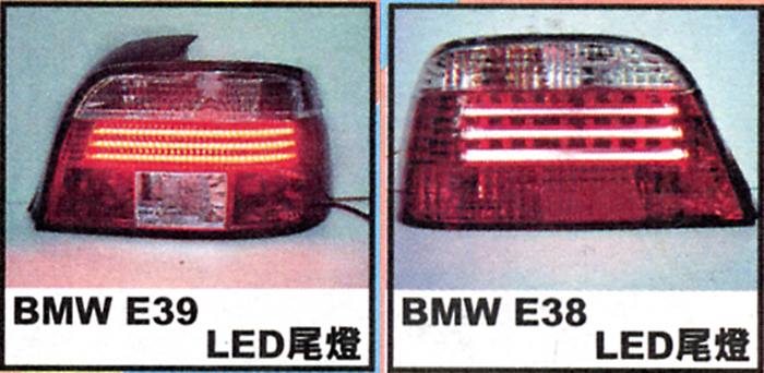
I have found these lights in HK too.
looks like we going to see other old BMW with these tube lights too.
I dont like any of these lights at all, very badly designed.
looks like we going to see other old BMW with these tube lights too.
I dont like any of these lights at all, very badly designed.
 05-16-2007, 01:43 PM
#362
Contributors

Join Date: Nov 2006
Location: High Desert, So. CA USA
Posts: 295
Likes: 0
Received 0 Likes
on
0 Posts
nick, from looking at your pins diagram. it is the correct and prefer way to hook up. the only drawback is the 3 back lightbulbs will wash out the lightrods. but there is an easy solution to it by hooking up some diodes.
if i remember correctly from taking the voltage reading...the taillight pin gives ~9 volts to the 3 backlight bulbs. each bulbs will be ~3V and appears on but not too bright. by installing a few diodes in series to the pin we can drastically reduce the voltage to those light bulb to a low value. this will make the light bulbs very dim and at the same time the LCM will still detect the lightbulbs and cause NO error message . diodes will allow electricity(current) to flow in one direction and cause a voltage drop called the foward voltage in data sheet. the voltage regulator zener diodes are used for voltage regulation. there are different values 3V-9V etc. by reversing a zener diode, we can use the value of the voltage regulation as a voltage drop too!
in electronic hardware store, there are many kind of diodes....but all diodes exhibit the forward voltage drop. silicone diodes will drop the voltage by ~.7v while other ones might drop ~1v. we can hook up a few of these diodes in series to get a desire voltage drop. about the power rating of the diode, the light bulbs at 21 watts with 12 voltage source, will draw about ~2 A of current. i recommend getting a diode with a minimum of 3 amperes. i hooked up one of the diode to the pin and was successful in getting a reduce voltage of 1V and this was expected since the particular 6 amp rectifier diode were designed to have a ~1v drop. i'm certain this solution will easily fix the aesthetic problem. i hope nick or someone else can give it a try very soon.
----------------------
i do NOT recommend my pin setup. in the further i'll have to rehook it again. as a few here have speculated i did use only the european fog or the big bottom center circle light bulb as my brake light. the brake light pin will always give a light when the parkinglight/headlight is switched to on. that is why i did not connect the tailight pin. however to trick the computer from not giving me the error msg, i connected the grey/green and black/red (pin 2 ,4, 7) all together i know this is a bad idea--i have 2 wires with different voltages, one is 9V, other one is 3V. what happens in this circuit, the output voltage will be 6V. however the current from the 9V wire will flow to the lower 3V wire too! assuming the battery has build in resistance, this will slowly drain the battery when car is not running and parkinglight is turned on. in addition, when brake is applied...voltage output goes to around 12.5V-13V. this will burn out the bulb prematurely if it didn't burn out right away. the next day i finally had a chance to correct the voltage problem by putting a diode to get it back safely under 12V. Again, i don't recommend this solution. i have some time, i'll need to rehook the wires back according to nick's diagram.
if i remember correctly from taking the voltage reading...the taillight pin gives ~9 volts to the 3 backlight bulbs. each bulbs will be ~3V and appears on but not too bright. by installing a few diodes in series to the pin we can drastically reduce the voltage to those light bulb to a low value. this will make the light bulbs very dim and at the same time the LCM will still detect the lightbulbs and cause NO error message . diodes will allow electricity(current) to flow in one direction and cause a voltage drop called the foward voltage in data sheet. the voltage regulator zener diodes are used for voltage regulation. there are different values 3V-9V etc. by reversing a zener diode, we can use the value of the voltage regulation as a voltage drop too!
in electronic hardware store, there are many kind of diodes....but all diodes exhibit the forward voltage drop. silicone diodes will drop the voltage by ~.7v while other ones might drop ~1v. we can hook up a few of these diodes in series to get a desire voltage drop. about the power rating of the diode, the light bulbs at 21 watts with 12 voltage source, will draw about ~2 A of current. i recommend getting a diode with a minimum of 3 amperes. i hooked up one of the diode to the pin and was successful in getting a reduce voltage of 1V and this was expected since the particular 6 amp rectifier diode were designed to have a ~1v drop. i'm certain this solution will easily fix the aesthetic problem.
i hope nick or someone else can give it a try very soon.----------------------
i do NOT recommend my pin setup. in the further i'll have to rehook it again. as a few here have speculated i did use only the european fog or the big bottom center circle light bulb as my brake light. the brake light pin will always give a light when the parkinglight/headlight is switched to on. that is why i did not connect the tailight pin. however to trick the computer from not giving me the error msg, i connected the grey/green and black/red (pin 2 ,4, 7) all together i know this is a bad idea--i have 2 wires with different voltages, one is 9V, other one is 3V. what happens in this circuit, the output voltage will be 6V. however the current from the 9V wire will flow to the lower 3V wire too! assuming the battery has build in resistance, this will slowly drain the battery when car is not running and parkinglight is turned on. in addition, when brake is applied...voltage output goes to around 12.5V-13V. this will burn out the bulb prematurely if it didn't burn out right away. the next day i finally had a chance to correct the voltage problem by putting a diode to get it back safely under 12V. Again, i don't recommend this solution. i have some time, i'll need to rehook the wires back according to nick's diagram.
 05-16-2007, 03:11 PM
#364
Contributors
Join Date: Dec 2004
Location: Brazil
Posts: 1,432
Likes: 0
Received 0 Likes
on
0 Posts
My Ride: 2007 E60 M5
Originally Posted by RootKit' post='425240' date='May 16 2007, 08:08 PM
 05-16-2007, 03:37 PM
#365
Contributors
Join Date: Nov 2006
Location: High Desert, So. CA USA
Posts: 295
Likes: 0
Received 0 Likes
on
0 Posts
Originally Posted by jayman098ma' post='424571' date='May 15 2007, 09:41 AM
RootKit, what is your wiring setup and what size of resistors did you use?
i had the blinker on for 10 minutes straight...the temperature on the resistor steady at
230F or 110C. good idea to put resistor against a metal frame of the car away
from plastic/cargo carpet. when blinking for a few seconds...it had virtually
no effect on the resistor(the resistor did not get warm at all). except for hazard light situation it is very unlikely you
will leave the blinker on for that long
 05-16-2007, 03:38 PM
#366
Contributors
Join Date: Jun 2005
Location: Chalandri/Athina/Hellas
Posts: 2,799
Likes: 0
Received 1 Like
on
1 Post
Very nice result The LCM is made to protect the car in any case, if something goes wrong (hyperloading or short circuit) it will cut off the current flowing into those wires and will give you an error message, so your mod is "somehow" secure. 
I'm trying to make a little circuit based on the LM338 regulator which can load up to 5-6A current, thus not so much heat, but I'm not ready yet. I'm very busy these days.
The LCM is made to protect the car in any case, if something goes wrong (hyperloading or short circuit) it will cut off the current flowing into those wires and will give you an error message, so your mod is "somehow" secure. I'm trying to make a little circuit based on the LM338 regulator which can load up to 5-6A current, thus not so much heat, but I'm not ready yet. I'm very busy these days.
05-16-2007, 04:12 PM
#368
Contributors
Join Date: Nov 2006
Location: High Desert, So. CA USA
Posts: 295
Likes: 0
Received 0 Likes
on
0 Posts
Originally Posted by Spig' post='425254' date='May 16 2007, 06:42 PM
Won't the diode suggestion lower the brightness of the brake lights too?
05-16-2007, 08:15 PM
#369
Contributors
Join Date: Nov 2006
Location: High Desert, So. CA USA
Posts: 295
Likes: 0
Received 0 Likes
on
0 Posts
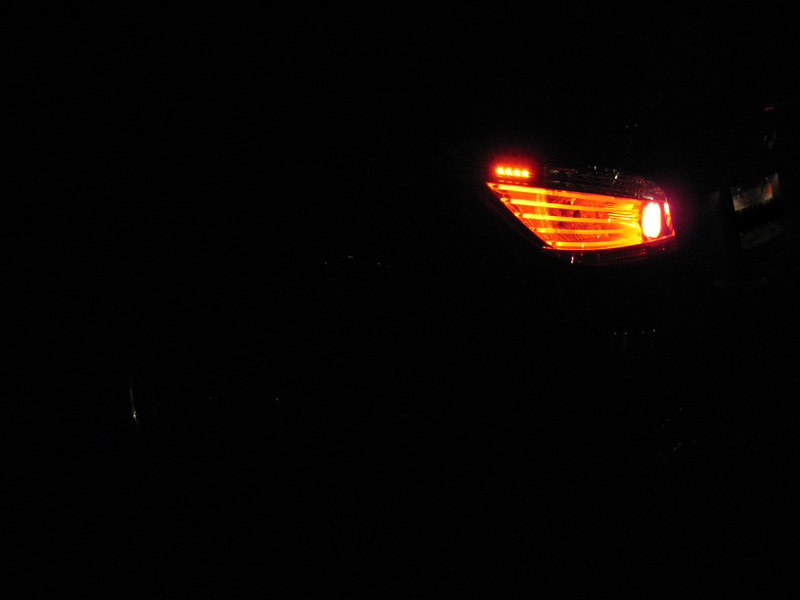
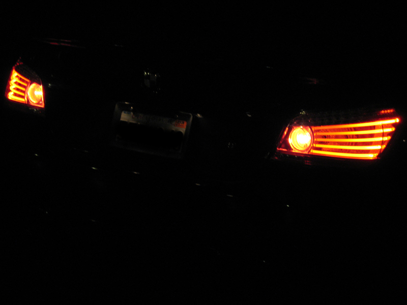
the diagram seems correct and the cable bruce made is plug and play. i'm more than ever starting to think the taillights will need some programming to get it to look exactly like the LCI cars. the programming control the power and the amount of power going thru the sections of the taillight.
however, nick is working on a solution. even though the temporary solution is not perfect LCI looks, the taillights still look very nice on the car!!
however, nick is working on a solution. even though the temporary solution is not perfect LCI looks, the taillights still look very nice on the car!!
05-18-2007, 05:21 PM
#370
Contributors

Join Date: Nov 2005
Location: London, UK
Posts: 4,719
Likes: 0
Received 3 Likes
on
3 Posts
My Ride: BMW E60 520d SE Saloon M47 2.0dTitanium Grey II, Grey−Dakota Leather, Visibility Package, Media Package, Through Load System, Lumbar support − fr seats, Automatic Air Conditioning−Advanced, High beam assistant, Hi−Fi Loudspeak
Model Year: 2006
Guys, I'm just back from holiday only to find my lights waiting for me. Still haven't opened the HUGE boxes.
Just wanted to say that I'll spend the weekend trying to make an LCI look cable. The circuit I'm using has been designed and will retain all the original functions of the taillight i.e. brake, BFD and fog. However it will look like the LCI lights on the normal tail light setting. Those who are interested in the currently release plug and play cables should not worry because if/when I make the LCI look cables I'll upgrade your cables for the price difference, so you'll get it for the same price.
My only problem at the moment is I'm relying of parts from UK so the over all cost is working out quite high. If people know good contacts to get BMW OEM parts cheap please PM me with the details.