
Replacing Front Tension/Wishbone Arms


Thread Starter
New Members
Joined: Jan 2013
Posts: 228
Likes: 0
From: atlanta
My Ride: 2005 545i Sport
2005 545i w/ Sport Suspension (Full Tank of Gas)
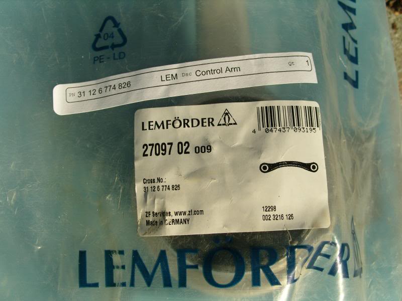
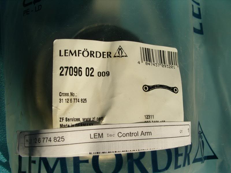
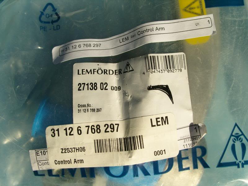
I used these control arms purchased from Amazon.com as they had the lowest delivered price by over $60 arriving at: $566.72:
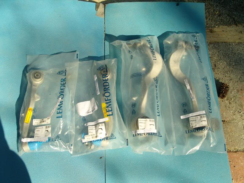
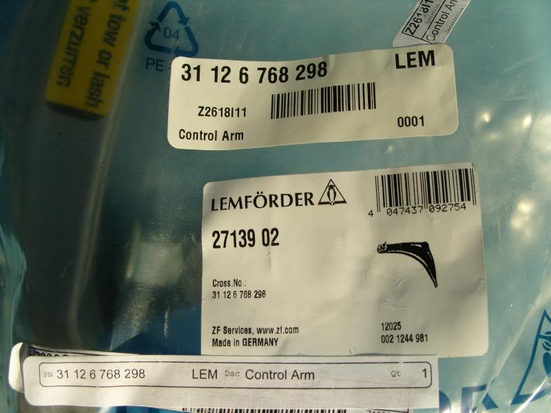
I also purchased all new bolts from my local BMW dealer. The arms come with two nuts per arm. You will need one additional nut for the hub/shock clamp.
I also purchased a 21mm box wrench from Sears, and I used a T40 extended wrench and socket. I consider these to be must buys to speed and professionally install the arms.
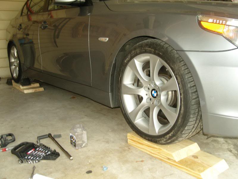
1. Back your car into the garage and onto wooden ramps as shown:
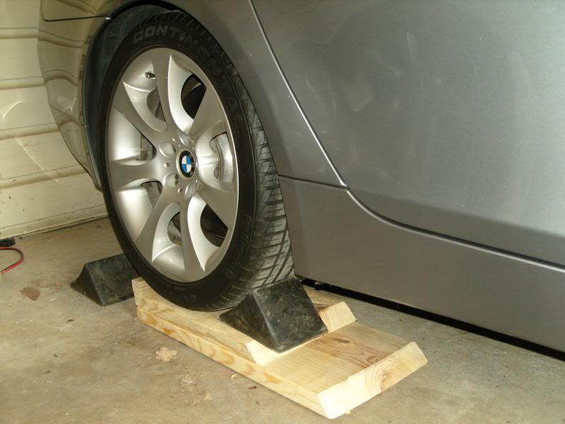
Ramps are made from a 2 x 12" with the lower level 28" long and the upper level 18" long with a stop and beveled front edge. (Even better, would be a base panel of 36" length, and a top panel of 24" length, so that the rubber chock can be fully seated on the wood)
The reason for placing the car in this manner is to provide greater natural light, ease of movement in front of vehicle, use of a trolley jack on the center jacking point, the garage floor is lowest by the door and for proper torqueing of the control arms to the subframe member.
2. Block wheels with rubber chocks and make sure that the parking brake is pulled tight.
3. Slightly loosen all lug nuts on front wheels.
4. Raise the vehicle using the center jacking point as shown:
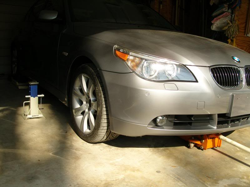
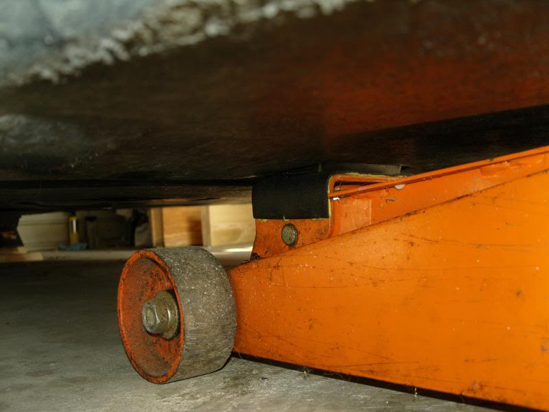
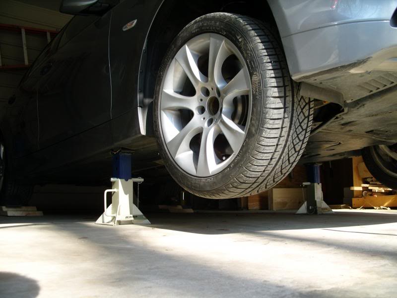
5. Place heavy duty jack stands (I use 7 ton) under the passenger and driver doors at their corresponding jack pads. I like to have good clearance, so I raise the vehicle quite high.
6. Lower vehicle onto jack stands and remove trolley jack.
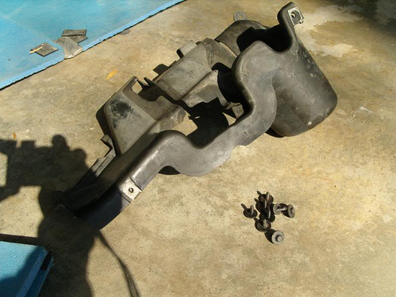
7. Remove the front under belly engine panel. (Quarter turn screws with a Phillips screwdriver).
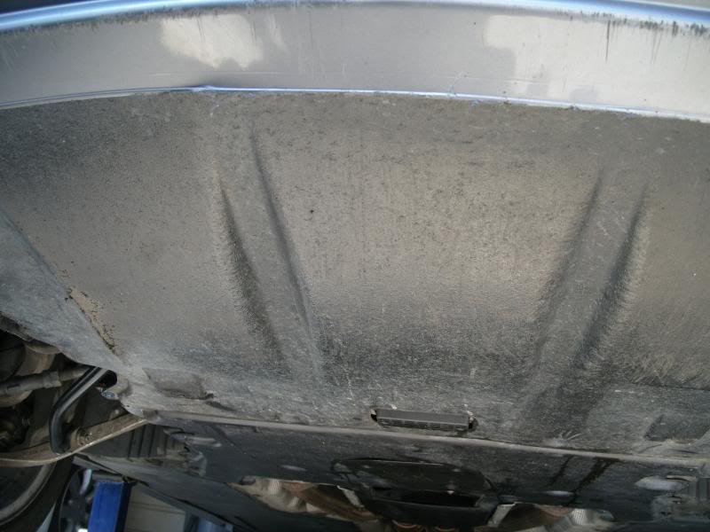
8. Remove the 8mm screws from the second under belly panel up to the transmission. There is no need to completely remove this panel. This will allow it to drop/free hang about 6 inches.
9. Remove the front wheels, and set aside with the lugs. (Thoroughly clean the wheel before reinstalling)
10. Remove the lower, inner fender panel, held in place with 8mm screws as shown:
This provides clean access to the control arms bolts/nuts at the subframe.This is critical when the car is brought to (Normal Position) prior to final torqueing of the new bolts.
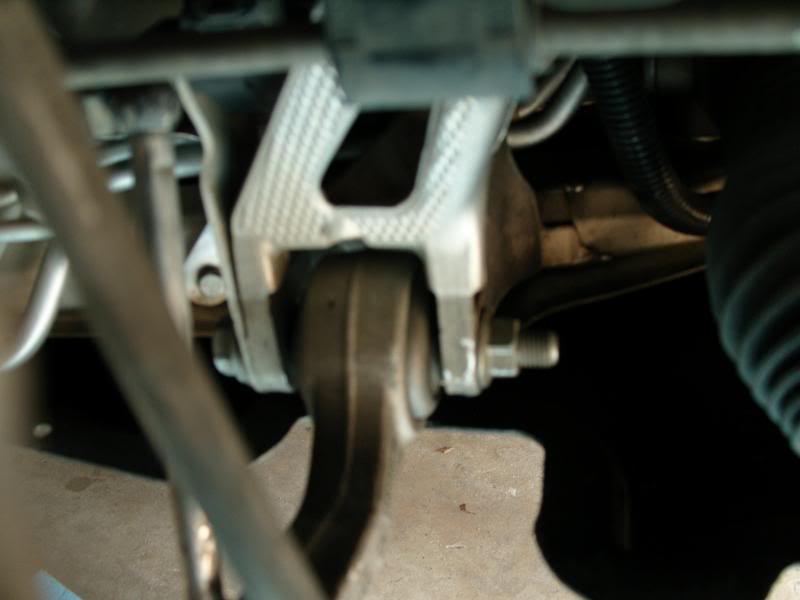
10b. On the passenger side, remove the leveling arm (10mm socket &wrench) from the wishbone arm as shown:
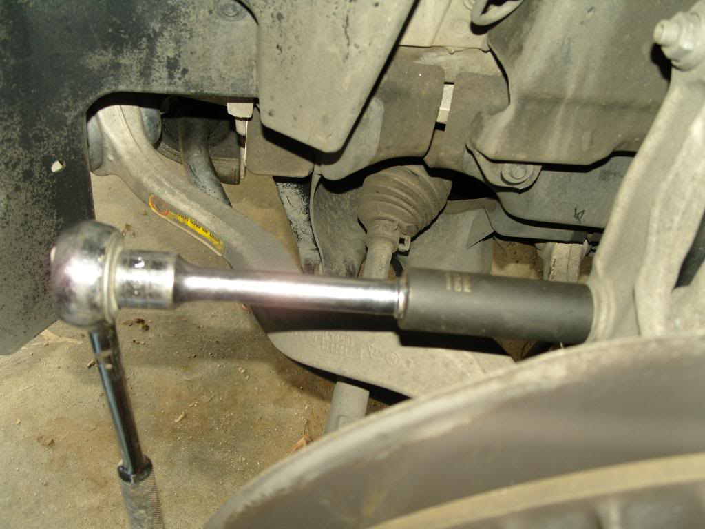
11. Using a 21mm deep well socket and a breaker bar loosen the nuts holding the spindle/knuckle end of the arms to the wheel hub (You have several options) as shown:
Using a 21mm deep wheel socket to loosen until the threaded stud spins with the nut
Using T40 hand wrench, 13/16" spark plug socket, 21mm open end wrench
Using T40 hand wrench, 21mm box wrench
Using T40 socket and 21mm box wrench
Loosen until the nut until it is flush with the top of the threaded spindle.
12. Using a scissor jack (better than a trolley/wheel jack) support the underside of the rotor by placing a piece of tool chest liner between the jack head and rotor. Raise the wheel assembly slightly and check for stability.
When you fully release the spindle/knuckle from the hub along with the control arm bolts at the subframe, the wheel assembly will want to shift and unless you lock the trolley jack in place, it will move with the hub assembly.
Also, a scissor jack is much more compact and allows for greater mobility around the hub assembly.
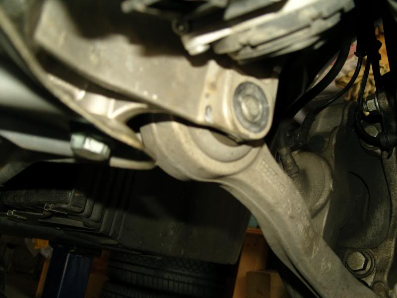
13. Using an 18mm socket x 2, or a 18mm open end wrench, loosen the bolt/nutholding the tension strut and wishbone arms to the subframe.
14. Now loosen and remove the clamp bolt/nut holding the strut (shock absorber) in place. It requires an 18mm socket with extension and a 18mm wrench or another 18mm socket.
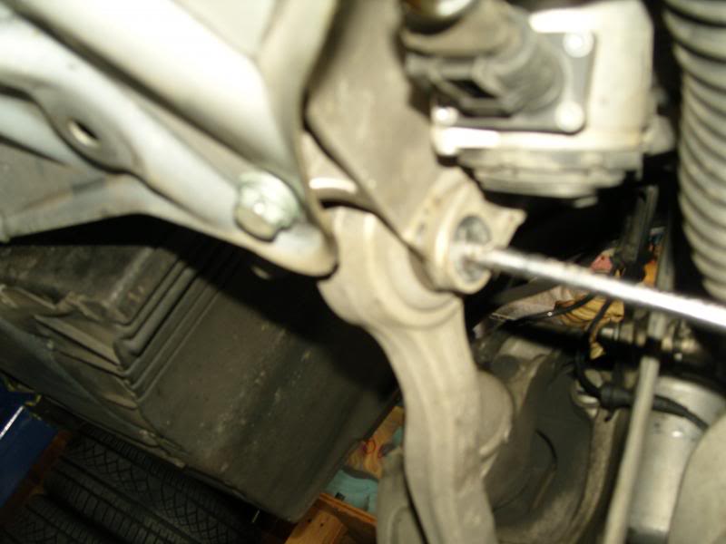
14. At the wishbone arm (that's the arm in the rear with the tension strut being the one upfront.) remove the the nut and bolt. The bolt can be wiggled out by hand, but I found taking a 1/4" socket extension arm and tapping it through the control arm pushed the bolt out much faster as shown:
15. With the spindle/knuckle nut (flush with the top of the threaded stud) on the wishbone arm, tap on the threaded stud with a steel mallet. Mine came out very easily.
16. Now tap on the arm to remove the arm from the subframe where it is now held in place with friction.
17. Take your new wishbone arm, bolt, and nut, and install the spindle/knuckle end into the hub assembly. Only slightly tighten so that much of the threaded stud is still visible (apply the same T40 and 21mm wrench technique as shown above):
18. Position the other end of the control arm into the subframe and using a new bolt/nut work it into place. Use a flashlight and a small mirror if you cannot get it to line-up to aid in positioning it correctly.
19. Tighten the bolt/nut so that only slight torque is holding it in place.
20 Move onto the tension strut by tapping the threaded stud on the spindle/knuckle in order to loosen from the hub assembly.
21. You must now raise the strut (shock absorber) so that the spindle/knuckle can be removed from the hub assembly.
22. I used a steel wedge and tapped it into the opening of the clamp area on the hub.
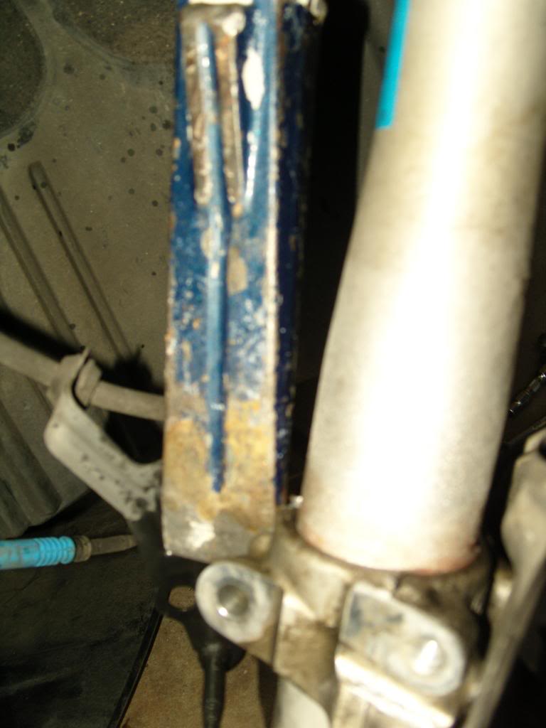
23. Spray Sea Foam penetrating lubricant onto the shock body near the hub so that it pours down onto the clamp area. I sprayed it 3 times.
24. Using a crow bar placed atop of the spindle and butted against the bottom of the shock body creates the ability to push up on the bottom of the shock in order to loosen it from the hub assembly and gain the needed space (about 1 inch).
25. If you own Coil Spring Compressors:
A. You can jack up the hub assembly (using a hydraulic jack) and place the coil compressor onto the compressed coil spring and snug it up by hand keeping it at 180 degrees from each other. Make sure you have clearance from the shock tower.
B. Now lower the hub assembly and the shock body might come loose from the hub assembly.
C. If it remains stuck, then using a steel mallet hit the hub assembly near the clamp area and spray with more penetrating lubricant until it frees itself.
26. Remove the tension strut spinde/knuckle and arm from the subframe.
27. Install the new spindle/knuckle into the hub and slightly tighten the nut
28. Position the other end of the arm into the subframe and work the new bolt/nut into position and only slightly tighten.
29. Install the new 18mm bolt/nut into the shock clamp and only slightly tighten.
30. Raise the rotor assembly until you hear/see the shock absorber move back into its original position.
31. Tighten the clamp bolt/nut to 81Nm (60lbs.) of torque.
32. Lower the jack but keep slight pressure on the rotor assembly.
33. Now fully tighten the new spindle/knuckle to 165 Nm (121 lbs) on both arms.
34. Tighten the bolt/nut at the subframe until it is slightly snug and then back off a 1/2 turn.
35. Reconnect the leveling arm to the wishbone arm and fully tighten.
36. Proceed in the same manner on the opposite front wheel of the vehicle.
37. You now have the spindle/knuckles fully torqued, but the control armbolt/nuts are not.
Obtaining “Normal Position” for final torqueing of subframe bolts
38. Now install the tires and snug up the wheel lugs as best as you can.
39. Raise the vehicle, and remove the jack stands, and lower the car onto the wooden ramps.
40. You must now obtain "Normal Position" before tightening the subframe bolts. BMW requires 150 lbs on each front seat and 150 lbs on the rear seat and 50lbs in the trunk on a full tank of gas.
41. I had 8 x 55lb boxes of marble tile that I placed as follows into the cab of the car: 3 boxes on the driver seat, 3 boxes on the passenger seat and 2 in the center of the rear seat. I also added one 50lb bag of cement into the center of the trunk.
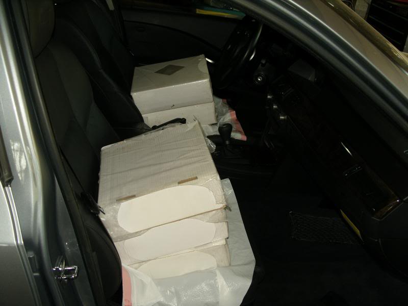
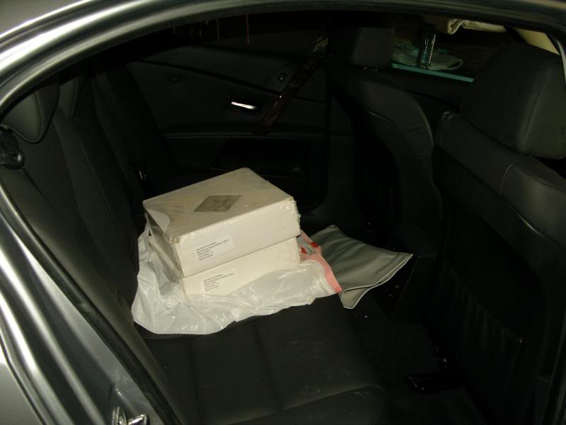
That's as close as I could come to "Normal Position".
If you don’t happen to have 500 lbs of material laying around; do this:
A. With the car on level ground, remove the center logo cap from your wheel and measure the distance from the center of the hub to the lip of the fender. Write this down. Mine was 15 ”
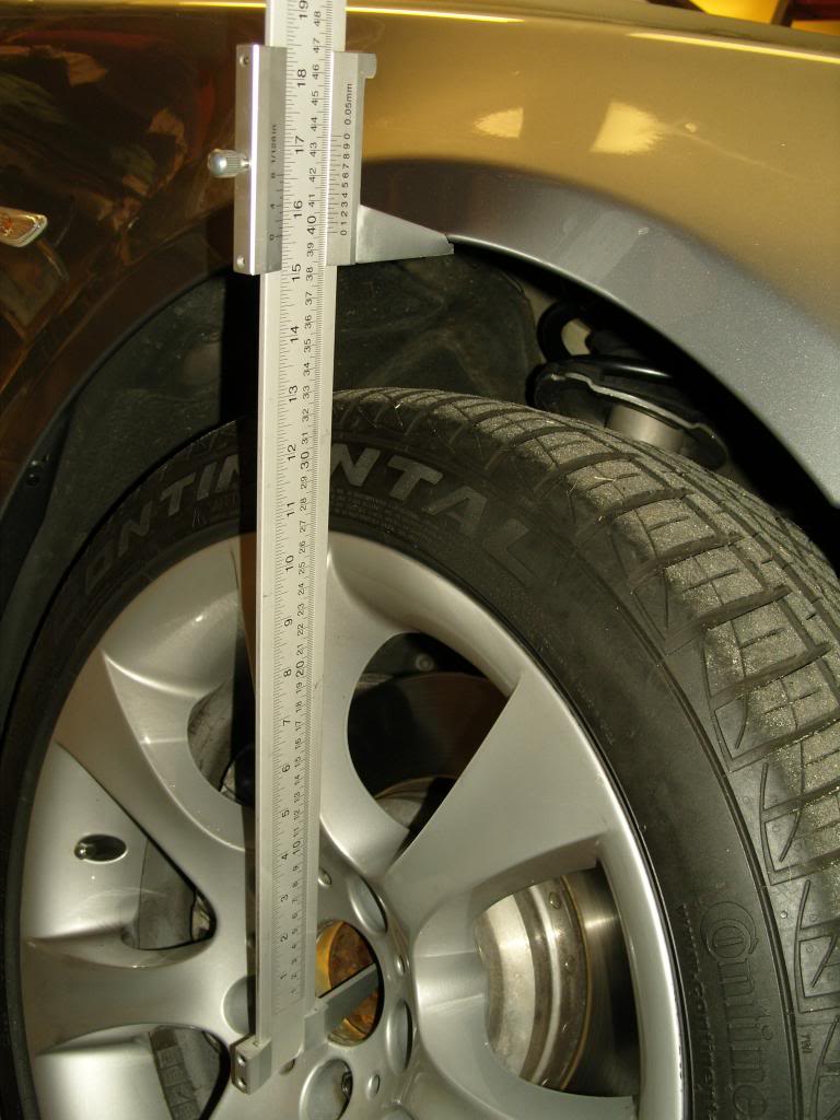
B. Now back to step 41; you want to jack up the hub assembly until the center hub is the distance you measured from step A less 1 to 1.5”. So on my car, it would have been 15 – 1.25 = 13.75”
C. This will require jacking the hub assembly so high that the car is lifted off of the jack stand in order to get the proper measurement. (This is why I used the wooden ramps)
D. With the hub assembly jacked up high; tighten the subframe bolts. Dangerous.
Proceeding back to Step 42 using the wooden ramp techique:
42. The extra 500 lbs of material in the cab/trunk of the car, lowers the vehicle about 1 to 1.5 inches and the car is now ready for the subframe bolts to be tightened.
43. Working in limited, but usable space (thanks to the ramps), torque the subframe bolts to 100 Nm (74 lbs)
44. Once properly torqued, remove the weights from inside the vehicle.
Is all this necessary?
Yes, if you don't preload the arms before final torque, you will dramatically cut the life of that rubber mount at the subframe.
Have you read about other posters complaining that their new arms only lasted 10K or 20k miles? That's because they didn't preload before tightening; it wasn't the result of Meyle, or Lemforder or Febi/Bilstein making bad product.
45. Loosen the wheel lugs
46. Jack the car back up, place jack stands, remove the front wooden ramps, and let it rest on the jack stands.
47. Remove the wheels and double check your torque.
48. Reinstall the inner wheel well panel and under belly panels.
49. Using brake cleaner or Xylenol clean your rotor facings before reinstalling the tires.
49. Raise car and remove jack stands and drive off the rear ramps.
50 Done.
I used these control arms purchased from Amazon.com as they had the lowest delivered price by over $60 arriving at: $566.72:
I also purchased all new bolts from my local BMW dealer. The arms come with two nuts per arm. You will need one additional nut for the hub/shock clamp.
I also purchased a 21mm box wrench from Sears, and I used a T40 extended wrench and socket. I consider these to be must buys to speed and professionally install the arms.
1. Back your car into the garage and onto wooden ramps as shown:
Ramps are made from a 2 x 12" with the lower level 28" long and the upper level 18" long with a stop and beveled front edge. (Even better, would be a base panel of 36" length, and a top panel of 24" length, so that the rubber chock can be fully seated on the wood)
The reason for placing the car in this manner is to provide greater natural light, ease of movement in front of vehicle, use of a trolley jack on the center jacking point, the garage floor is lowest by the door and for proper torqueing of the control arms to the subframe member.
2. Block wheels with rubber chocks and make sure that the parking brake is pulled tight.
3. Slightly loosen all lug nuts on front wheels.
4. Raise the vehicle using the center jacking point as shown:
5. Place heavy duty jack stands (I use 7 ton) under the passenger and driver doors at their corresponding jack pads. I like to have good clearance, so I raise the vehicle quite high.
6. Lower vehicle onto jack stands and remove trolley jack.
7. Remove the front under belly engine panel. (Quarter turn screws with a Phillips screwdriver).
8. Remove the 8mm screws from the second under belly panel up to the transmission. There is no need to completely remove this panel. This will allow it to drop/free hang about 6 inches.
9. Remove the front wheels, and set aside with the lugs. (Thoroughly clean the wheel before reinstalling)
10. Remove the lower, inner fender panel, held in place with 8mm screws as shown:
This provides clean access to the control arms bolts/nuts at the subframe.This is critical when the car is brought to (Normal Position) prior to final torqueing of the new bolts.
10b. On the passenger side, remove the leveling arm (10mm socket &wrench) from the wishbone arm as shown:
11. Using a 21mm deep well socket and a breaker bar loosen the nuts holding the spindle/knuckle end of the arms to the wheel hub (You have several options) as shown:
Using a 21mm deep wheel socket to loosen until the threaded stud spins with the nut
Using T40 hand wrench, 13/16" spark plug socket, 21mm open end wrench
Using T40 hand wrench, 21mm box wrench
Using T40 socket and 21mm box wrench
Loosen until the nut until it is flush with the top of the threaded spindle.
12. Using a scissor jack (better than a trolley/wheel jack) support the underside of the rotor by placing a piece of tool chest liner between the jack head and rotor. Raise the wheel assembly slightly and check for stability.
When you fully release the spindle/knuckle from the hub along with the control arm bolts at the subframe, the wheel assembly will want to shift and unless you lock the trolley jack in place, it will move with the hub assembly.
Also, a scissor jack is much more compact and allows for greater mobility around the hub assembly.
13. Using an 18mm socket x 2, or a 18mm open end wrench, loosen the bolt/nutholding the tension strut and wishbone arms to the subframe.
14. Now loosen and remove the clamp bolt/nut holding the strut (shock absorber) in place. It requires an 18mm socket with extension and a 18mm wrench or another 18mm socket.
14. At the wishbone arm (that's the arm in the rear with the tension strut being the one upfront.) remove the the nut and bolt. The bolt can be wiggled out by hand, but I found taking a 1/4" socket extension arm and tapping it through the control arm pushed the bolt out much faster as shown:
15. With the spindle/knuckle nut (flush with the top of the threaded stud) on the wishbone arm, tap on the threaded stud with a steel mallet. Mine came out very easily.
16. Now tap on the arm to remove the arm from the subframe where it is now held in place with friction.
17. Take your new wishbone arm, bolt, and nut, and install the spindle/knuckle end into the hub assembly. Only slightly tighten so that much of the threaded stud is still visible (apply the same T40 and 21mm wrench technique as shown above):
18. Position the other end of the control arm into the subframe and using a new bolt/nut work it into place. Use a flashlight and a small mirror if you cannot get it to line-up to aid in positioning it correctly.
19. Tighten the bolt/nut so that only slight torque is holding it in place.
20 Move onto the tension strut by tapping the threaded stud on the spindle/knuckle in order to loosen from the hub assembly.
21. You must now raise the strut (shock absorber) so that the spindle/knuckle can be removed from the hub assembly.
22. I used a steel wedge and tapped it into the opening of the clamp area on the hub.
23. Spray Sea Foam penetrating lubricant onto the shock body near the hub so that it pours down onto the clamp area. I sprayed it 3 times.
24. Using a crow bar placed atop of the spindle and butted against the bottom of the shock body creates the ability to push up on the bottom of the shock in order to loosen it from the hub assembly and gain the needed space (about 1 inch).
25. If you own Coil Spring Compressors:
A. You can jack up the hub assembly (using a hydraulic jack) and place the coil compressor onto the compressed coil spring and snug it up by hand keeping it at 180 degrees from each other. Make sure you have clearance from the shock tower.
B. Now lower the hub assembly and the shock body might come loose from the hub assembly.
C. If it remains stuck, then using a steel mallet hit the hub assembly near the clamp area and spray with more penetrating lubricant until it frees itself.
26. Remove the tension strut spinde/knuckle and arm from the subframe.
27. Install the new spindle/knuckle into the hub and slightly tighten the nut
28. Position the other end of the arm into the subframe and work the new bolt/nut into position and only slightly tighten.
29. Install the new 18mm bolt/nut into the shock clamp and only slightly tighten.
30. Raise the rotor assembly until you hear/see the shock absorber move back into its original position.
31. Tighten the clamp bolt/nut to 81Nm (60lbs.) of torque.
32. Lower the jack but keep slight pressure on the rotor assembly.
33. Now fully tighten the new spindle/knuckle to 165 Nm (121 lbs) on both arms.
34. Tighten the bolt/nut at the subframe until it is slightly snug and then back off a 1/2 turn.
35. Reconnect the leveling arm to the wishbone arm and fully tighten.
36. Proceed in the same manner on the opposite front wheel of the vehicle.
37. You now have the spindle/knuckles fully torqued, but the control armbolt/nuts are not.
Obtaining “Normal Position” for final torqueing of subframe bolts
38. Now install the tires and snug up the wheel lugs as best as you can.
39. Raise the vehicle, and remove the jack stands, and lower the car onto the wooden ramps.
40. You must now obtain "Normal Position" before tightening the subframe bolts. BMW requires 150 lbs on each front seat and 150 lbs on the rear seat and 50lbs in the trunk on a full tank of gas.
41. I had 8 x 55lb boxes of marble tile that I placed as follows into the cab of the car: 3 boxes on the driver seat, 3 boxes on the passenger seat and 2 in the center of the rear seat. I also added one 50lb bag of cement into the center of the trunk.
That's as close as I could come to "Normal Position".
If you don’t happen to have 500 lbs of material laying around; do this:
A. With the car on level ground, remove the center logo cap from your wheel and measure the distance from the center of the hub to the lip of the fender. Write this down. Mine was 15 ”
B. Now back to step 41; you want to jack up the hub assembly until the center hub is the distance you measured from step A less 1 to 1.5”. So on my car, it would have been 15 – 1.25 = 13.75”
C. This will require jacking the hub assembly so high that the car is lifted off of the jack stand in order to get the proper measurement. (This is why I used the wooden ramps)
D. With the hub assembly jacked up high; tighten the subframe bolts. Dangerous.
Proceeding back to Step 42 using the wooden ramp techique:
42. The extra 500 lbs of material in the cab/trunk of the car, lowers the vehicle about 1 to 1.5 inches and the car is now ready for the subframe bolts to be tightened.
43. Working in limited, but usable space (thanks to the ramps), torque the subframe bolts to 100 Nm (74 lbs)
44. Once properly torqued, remove the weights from inside the vehicle.
Is all this necessary?
Yes, if you don't preload the arms before final torque, you will dramatically cut the life of that rubber mount at the subframe.
Have you read about other posters complaining that their new arms only lasted 10K or 20k miles? That's because they didn't preload before tightening; it wasn't the result of Meyle, or Lemforder or Febi/Bilstein making bad product.
45. Loosen the wheel lugs
46. Jack the car back up, place jack stands, remove the front wooden ramps, and let it rest on the jack stands.
47. Remove the wheels and double check your torque.
48. Reinstall the inner wheel well panel and under belly panels.
49. Using brake cleaner or Xylenol clean your rotor facings before reinstalling the tires.
49. Raise car and remove jack stands and drive off the rear ramps.
50 Done.
Last edited by paran; Apr 1, 2013 at 01:30 PM.

Thread Starter
New Members
Joined: Jan 2013
Posts: 228
Likes: 0
From: atlanta
My Ride: 2005 545i Sport
By preloading the car to "normal position", you take the stress off of the rubber bushings at the subframe. This effort is designed to alleviate that problem, but it doesn't make the vehicle sit any lower.
The arms were date stamped 2004 and original to the vehicle. Upon removal, I could see cracks in the rubber, but while it was mounted, I could not.

Members
Senior Members
Joined: May 2012
Posts: 297
Likes: 1
From: USA
My Ride: Sold: 545i, sport package, cold weather, 6MT
Model Year: 2004
Engine: N62
Great write up,
Mileage on car?
Time to complete?
Did you feel anything before the change when you would turn your wheel all the way right or left?
Mileage on car?
Time to complete?
Did you feel anything before the change when you would turn your wheel all the way right or left?
Thread Starter
New Members
Joined: Jan 2013
Posts: 228
Likes: 0
From: atlanta
My Ride: 2005 545i Sport
It has 99.4K miles on it.
It took me 6 hours as I recall.
The only issue I noticed at it was a slight thunk and slight lurch forward after a somewhat hard stop. Turning left/right didn't equate to any concerns.
I could have stayed on them but why do that with an alignment on the immediate horizon.
I know a lot of guys skip the preloading before torqueing the bolts but that will only lead to a shortened life span.

Members
Senior Members
Joined: May 2005
Posts: 1,525
Likes: 53
From: Denver, USA
My Ride: 2006 BMW 530xi 6MT
Model Year: 2006
Engine: N52
Has anyone done this on an xdrive car? I have the Bentley manual and it looks a lot easier in that there is no need to remove the shock strut from the steering knuckle.
New Members
Joined: Sep 2012
Posts: 477
Likes: 12
From: Halifax, Nova Scotia, Canada
My Ride: 2004 545i+BT+AUX+Coding
Model Year: 2004
Engine: N62
2005 545i w/ Sport Suspension (Full Tank of Gas)
I used these control arms purchased from Amazon.com as they had the lowest delivered price by over $60 arriving at: $566.72:
Attachment 162160
Attachment 162161Attachment 162162Attachment 162163Attachment 162164
I also purchased all new bolts from my local BMW dealer. The arms come with two nuts per arm. You will need one additional nut for the hub/shock clamp.
I also purchased a 21mm box wrench from Sears, and I used a T40 extended wrench and socket. I consider these to be must buys to speed and professionally install the arms.
1. Back your car into the garage and onto wooden ramps as shown:
Attachment 162165
Ramps are made from a 2 x 12" with the lower level 28" long and the upper level 18" long with a stop and beveled front edge. (Even better, would be a base panel of 36" length, and a top panel of 24" length, so that the rubber chock can be fully seated on the wood)
The reason for placing the car in this manner is to provide greater natural light, ease of movement in front of vehicle, use of a trolley jack on the center jacking point, the garage floor is lowest by the door and for proper torqueing of the control arms to the subframe member.
2. Block wheels with rubber chocks and make sure that the parking brake is pulled tight.
3. Slightly loosen all lug nuts on front wheels.
4. Raise the vehicle using the center jacking point as shown:
Attachment 162166 Attachment 162167
5. Place heavy duty jack stands (I use 7 ton) under the passenger and driver doors at their corresponding jack pads. I like to have good clearance, so I raise the vehicle quite high.
Attachment 162168
6. Lower vehicle onto jack stands and remove trolley jack.
7. Remove the front under belly engine panel. (Quarter turn screws with a Phillips screwdriver).
Attachment 162169
8. Remove the 8mm screws from the second under belly panel up to the transmission. There is no need to completely remove this panel. This will allow it to drop/free hang about 6 inches.
9. Remove the front wheels, and set aside with the lugs. (Thoroughly clean the wheel before reinstalling)
10. Remove the lower, inner fender panel, held in place with 8mm screws as shown:
Attachment 162170
This provides clean access to the control arms bolts/nuts at the subframe.This is critical when the car is brought to (Normal Position) prior to final torqueing of the new bolts.
Attachment 162171
10b. On the passenger side, remove the leveling arm (10mm socket &wrench) from the wishbone arm as shown:
Attachment 162172
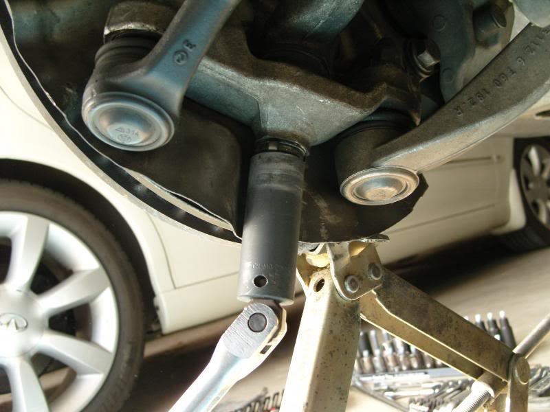
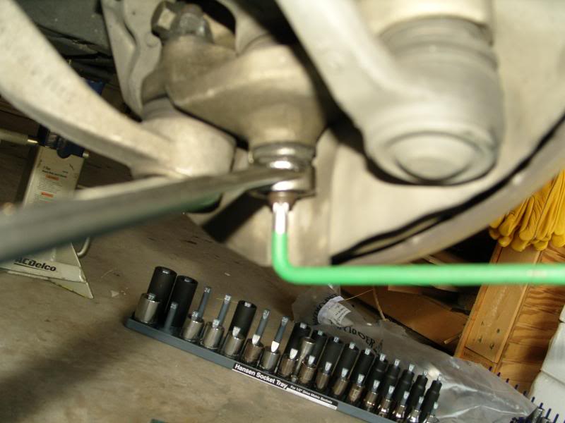
11. Using a 21mm deep well socket and a breaker bar loosen the nuts holding the spindle/knuckle end of the arms to the wheel hub (You have several options) as shown:
Attachment 162173
Using a 21mm deep wheel socket to loosen until the threaded stud spins with the nut
Attachment 162174
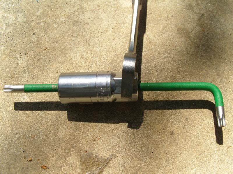
Using T40 hand wrench, 13/16" spark plug socket, 21mm open end wrench
Attachment 162175
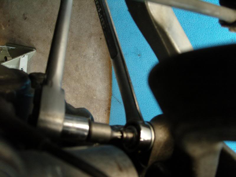
Using T40 hand wrench, 21mm box wrench
Attachment 162177
Using T40 socket and 21mm box wrench
Attachment 162178
Loosen until the nut until it is flush with the top of the threaded spindle.
12. Using a scissor jack (better than a trolley/wheel jack) support the underside of the rotor by placing a piece of tool chest liner between the jack head and rotor. Raise the wheel assembly slightly and check for stability.
When you fully release the spindle/knuckle from the hub along with the control arm bolts at the subframe, the wheel assembly will want to shift and unless you lock the trolley jack in place, it will move with the hub assembly.
Also, a scissor jack is much more compact and allows for greater mobility around the hub assembly.
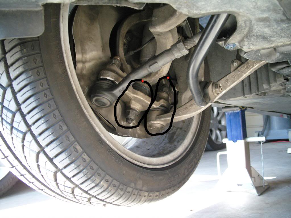
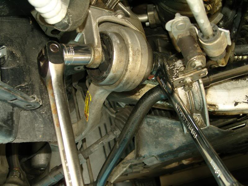
13. Using an 18mm socket x 2, or a 18mm open end wrench, loosen the bolt/nutholding the tension strut and wishbone arms to the subframe.
Attachment 162179
Attachment 162180
14. Now loosen and remove the clamp bolt/nut holding the strut (shock absorber) in place. It requires an 18mm socket with extension and a 18mm wrench or another 18mm socket.
Attachment 162181
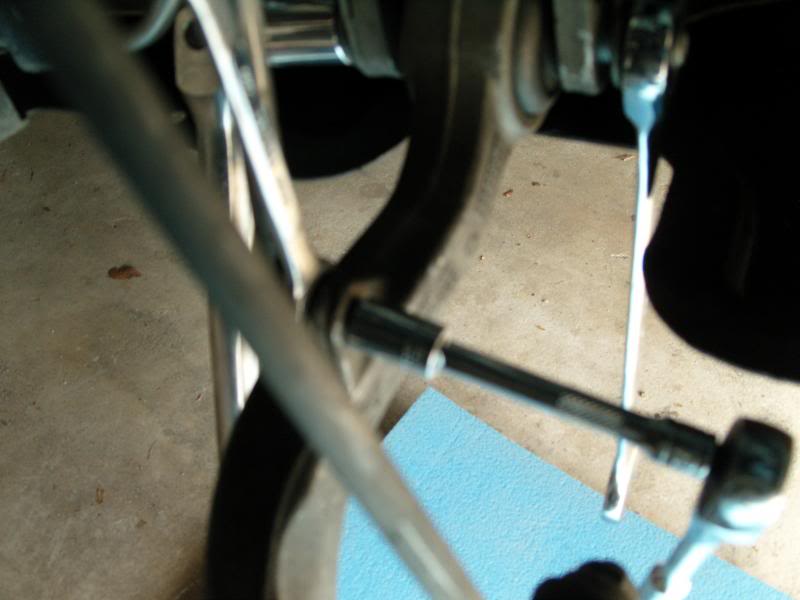
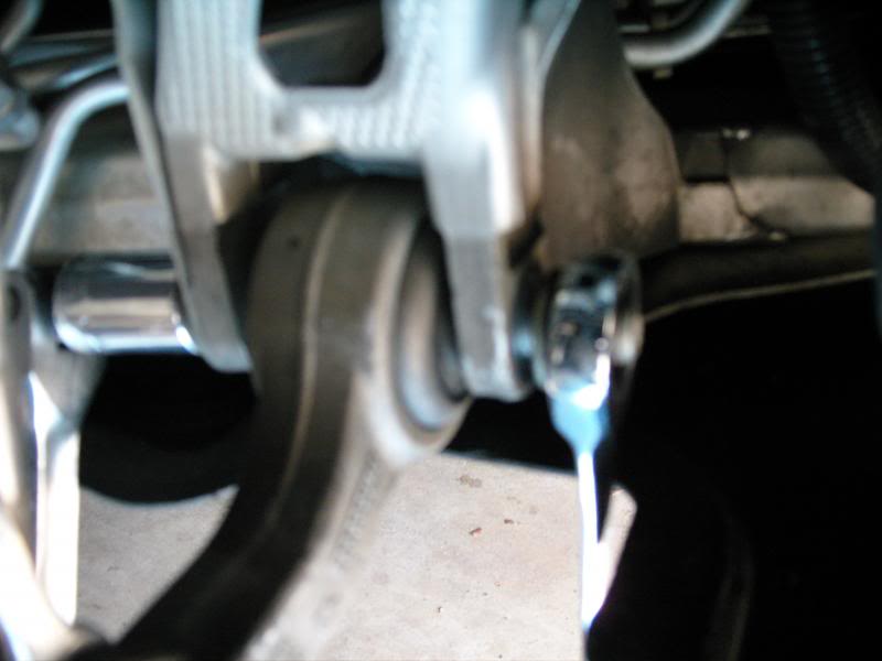
14. At the wishbone arm (that's the arm in the rear with the tension strut being the one upfront.) remove the the nut and bolt. The bolt can be wiggled out by hand, but I found taking a 1/4" socket extension arm and tapping it through the control arm pushed the bolt out much faster as shown:
Attachment 162182
Attachment 162183
15. With the spindle/knuckle nut (flush with the top of the threaded stud) on the wishbone arm, tap on the threaded stud with a steel mallet. Mine came out very easily.
16. Now tap on the arm to remove the arm from the subframe where it is now held in place with friction.
17. Take your new wishbone arm, bolt, and nut, and install the spindle/knuckle end into the hub assembly. Only slightly tighten so that much of the threaded stud is still visible (apply the same T40 and 21mm wrench technique as shown above):
18. Position the other end of the control arm into the subframe and using a new bolt/nut work it into place. Use a flashlight and a small mirror if you cannot get it to line-up to aid in positioning it correctly.
19. Tighten the bolt/nut so that only slight torque is holding it in place.
20 Move onto the tension strut by tapping the threaded stud on the spindle/knuckle in order to loosen from the hub assembly.
21. You must now raise the strut (shock absorber) so that the spindle/knuckle can be removed from the hub assembly.
22. I used a steel wedge and tapped it into the opening of the clamp area on the hub.
Attachment 162184
23. Spray Sea Foam penetrating lubricant onto the shock body near the hub so that it pours down onto the clamp area. I sprayed it 3 times.
24. Using a crow bar placed atop of the spindle and butted against the bottom of the shock body creates the ability to push up on the bottom of the shock in order to loosen it from the hub assembly and gain the needed space (about 1 inch).
25. If you own Coil Spring Compressors:
A. You can jack up the hub assembly (using a hydraulic jack) and place the coil compressor onto the compressed coil spring and snug it up by hand keeping it at 180 degrees from each other. Make sure you have clearance from the shock tower.
B. Now lower the hub assembly and the shock body might come loose from the hub assembly.
C. If it remains stuck, then using a steel mallet hit the hub assembly near the clamp area and spray with more penetrating lubricant until it frees itself.
26. Remove the tension strut spinde/knuckle and arm from the subframe.
27. Install the new spindle/knuckle into the hub and slightly tighten the nut
28. Position the other end of the arm into the subframe and work the new bolt/nut into position and only slightly tighten.
29. Install the new 18mm bolt/nut into the shock clamp and only slightly tighten.
30. Raise the rotor assembly until you hear/see the shock absorber move back into its original position.
31. Tighten the clamp bolt/nut to 81Nm (60lbs.) of torque.
32. Lower the jack but keep slight pressure on the rotor assembly.
33. Now fully tighten the new spindle/knuckle to 165 Nm (121 lbs) on both arms.
34. Tighten the bolt/nut at the subframe until it is slightly snug and then back off a 1/2 turn.
35. Reconnect the leveling arm to the wishbone arm and fully tighten.
36. Proceed in the same manner on the opposite front wheel of the vehicle.
37. You now have the spindle/knuckles fully torqued, but the control armbolt/nuts are not.
Obtaining “Normal Position” for final torqueing of subframe bolts
38. Now install the tires and snug up the wheel lugs as best as you can.
39. Raise the vehicle, and remove the jack stands, and lower the car onto the wooden ramps.
Attachment 162185
40. You must now obtain "Normal Position" before tightening the subframe bolts. BMW requires 150 lbs on each front seat and 150 lbs on the rear seat and 50lbs in the trunk on a full tank of gas.
41. I had 8 x 55lb boxes of marble tile that I placed as follows into the cab of the car: 3 boxes on the driver seat, 3 boxes on the passenger seat and 2 in the center of the rear seat. I also added one 50lb bag of cement into the center of the trunk.
Attachment 162186
Attachment 162187
That's as close as I could come to "Normal Position".
If you don’t happen to have 500 lbs of material laying around; do this:
A. With the car on level ground, remove the center logo cap from your wheel and measure the distance from the center of the hub to the lip of the fender. Write this down. Mine was 15 ”
Attachment 162188
B. Now back to step 41; you want to jack up the hub assembly until the center hub is the distance you measured from step A less 1 to 1.5”. So on my car, it would have been 15 – 1.25 = 13.75”
C. This will require jacking the hub assembly so high that the car is lifted off of the jack stand in order to get the proper measurement. (This is why I used the wooden ramps)
D. With the hub assembly jacked up high; tighten the subframe bolts. Dangerous.
Proceeding back to Step 42 using the wooden ramp techique:
42. The extra 500 lbs of material in the cab/trunk of the car, lowers the vehicle about 1 to 1.5 inches and the car is now ready for the subframe bolts to be tightened.
43. Working in limited, but usable space (thanks to the ramps), torque the subframe bolts to 100 Nm (74 lbs)
44. Once properly torqued, remove the weights from inside the vehicle.
Is all this necessary?
Yes, if you don't preload the arms before final torque, you will dramatically cut the life of that rubber mount at the subframe.
Have you read about other posters complaining that their new arms only lasted 10K or 20k miles? That's because they didn't preload before tightening; it wasn't the result of Meyle, or Lemforder or Febi/Bilstein making bad product.
45. Loosen the wheel lugs
46. Jack the car back up, place jack stands, remove the front wooden ramps, and let it rest on the jack stands.
47. Remove the wheels and double check your torque.
48. Reinstall the inner wheel well panel and under belly panels.
49. Using brake cleaner or Xylenol clean your rotor facings before reinstalling the tires.
49. Raise car and remove jack stands and drive off the rear ramps.
50 Done.
I used these control arms purchased from Amazon.com as they had the lowest delivered price by over $60 arriving at: $566.72:
Attachment 162160
Attachment 162161Attachment 162162Attachment 162163Attachment 162164
I also purchased all new bolts from my local BMW dealer. The arms come with two nuts per arm. You will need one additional nut for the hub/shock clamp.
I also purchased a 21mm box wrench from Sears, and I used a T40 extended wrench and socket. I consider these to be must buys to speed and professionally install the arms.
1. Back your car into the garage and onto wooden ramps as shown:
Attachment 162165
Ramps are made from a 2 x 12" with the lower level 28" long and the upper level 18" long with a stop and beveled front edge. (Even better, would be a base panel of 36" length, and a top panel of 24" length, so that the rubber chock can be fully seated on the wood)
The reason for placing the car in this manner is to provide greater natural light, ease of movement in front of vehicle, use of a trolley jack on the center jacking point, the garage floor is lowest by the door and for proper torqueing of the control arms to the subframe member.
2. Block wheels with rubber chocks and make sure that the parking brake is pulled tight.
3. Slightly loosen all lug nuts on front wheels.
4. Raise the vehicle using the center jacking point as shown:
Attachment 162166 Attachment 162167
5. Place heavy duty jack stands (I use 7 ton) under the passenger and driver doors at their corresponding jack pads. I like to have good clearance, so I raise the vehicle quite high.
Attachment 162168
6. Lower vehicle onto jack stands and remove trolley jack.
7. Remove the front under belly engine panel. (Quarter turn screws with a Phillips screwdriver).
Attachment 162169
8. Remove the 8mm screws from the second under belly panel up to the transmission. There is no need to completely remove this panel. This will allow it to drop/free hang about 6 inches.
9. Remove the front wheels, and set aside with the lugs. (Thoroughly clean the wheel before reinstalling)
10. Remove the lower, inner fender panel, held in place with 8mm screws as shown:
Attachment 162170
This provides clean access to the control arms bolts/nuts at the subframe.This is critical when the car is brought to (Normal Position) prior to final torqueing of the new bolts.
Attachment 162171
10b. On the passenger side, remove the leveling arm (10mm socket &wrench) from the wishbone arm as shown:
Attachment 162172
11. Using a 21mm deep well socket and a breaker bar loosen the nuts holding the spindle/knuckle end of the arms to the wheel hub (You have several options) as shown:
Attachment 162173
Using a 21mm deep wheel socket to loosen until the threaded stud spins with the nut
Attachment 162174
Using T40 hand wrench, 13/16" spark plug socket, 21mm open end wrench
Attachment 162175
Using T40 hand wrench, 21mm box wrench
Attachment 162177
Using T40 socket and 21mm box wrench
Attachment 162178
Loosen until the nut until it is flush with the top of the threaded spindle.
12. Using a scissor jack (better than a trolley/wheel jack) support the underside of the rotor by placing a piece of tool chest liner between the jack head and rotor. Raise the wheel assembly slightly and check for stability.
When you fully release the spindle/knuckle from the hub along with the control arm bolts at the subframe, the wheel assembly will want to shift and unless you lock the trolley jack in place, it will move with the hub assembly.
Also, a scissor jack is much more compact and allows for greater mobility around the hub assembly.
13. Using an 18mm socket x 2, or a 18mm open end wrench, loosen the bolt/nutholding the tension strut and wishbone arms to the subframe.
Attachment 162179
Attachment 162180
14. Now loosen and remove the clamp bolt/nut holding the strut (shock absorber) in place. It requires an 18mm socket with extension and a 18mm wrench or another 18mm socket.
Attachment 162181
14. At the wishbone arm (that's the arm in the rear with the tension strut being the one upfront.) remove the the nut and bolt. The bolt can be wiggled out by hand, but I found taking a 1/4" socket extension arm and tapping it through the control arm pushed the bolt out much faster as shown:
Attachment 162182
Attachment 162183
15. With the spindle/knuckle nut (flush with the top of the threaded stud) on the wishbone arm, tap on the threaded stud with a steel mallet. Mine came out very easily.
16. Now tap on the arm to remove the arm from the subframe where it is now held in place with friction.
17. Take your new wishbone arm, bolt, and nut, and install the spindle/knuckle end into the hub assembly. Only slightly tighten so that much of the threaded stud is still visible (apply the same T40 and 21mm wrench technique as shown above):
18. Position the other end of the control arm into the subframe and using a new bolt/nut work it into place. Use a flashlight and a small mirror if you cannot get it to line-up to aid in positioning it correctly.
19. Tighten the bolt/nut so that only slight torque is holding it in place.
20 Move onto the tension strut by tapping the threaded stud on the spindle/knuckle in order to loosen from the hub assembly.
21. You must now raise the strut (shock absorber) so that the spindle/knuckle can be removed from the hub assembly.
22. I used a steel wedge and tapped it into the opening of the clamp area on the hub.
Attachment 162184
23. Spray Sea Foam penetrating lubricant onto the shock body near the hub so that it pours down onto the clamp area. I sprayed it 3 times.
24. Using a crow bar placed atop of the spindle and butted against the bottom of the shock body creates the ability to push up on the bottom of the shock in order to loosen it from the hub assembly and gain the needed space (about 1 inch).
25. If you own Coil Spring Compressors:
A. You can jack up the hub assembly (using a hydraulic jack) and place the coil compressor onto the compressed coil spring and snug it up by hand keeping it at 180 degrees from each other. Make sure you have clearance from the shock tower.
B. Now lower the hub assembly and the shock body might come loose from the hub assembly.
C. If it remains stuck, then using a steel mallet hit the hub assembly near the clamp area and spray with more penetrating lubricant until it frees itself.
26. Remove the tension strut spinde/knuckle and arm from the subframe.
27. Install the new spindle/knuckle into the hub and slightly tighten the nut
28. Position the other end of the arm into the subframe and work the new bolt/nut into position and only slightly tighten.
29. Install the new 18mm bolt/nut into the shock clamp and only slightly tighten.
30. Raise the rotor assembly until you hear/see the shock absorber move back into its original position.
31. Tighten the clamp bolt/nut to 81Nm (60lbs.) of torque.
32. Lower the jack but keep slight pressure on the rotor assembly.
33. Now fully tighten the new spindle/knuckle to 165 Nm (121 lbs) on both arms.
34. Tighten the bolt/nut at the subframe until it is slightly snug and then back off a 1/2 turn.
35. Reconnect the leveling arm to the wishbone arm and fully tighten.
36. Proceed in the same manner on the opposite front wheel of the vehicle.
37. You now have the spindle/knuckles fully torqued, but the control armbolt/nuts are not.
Obtaining “Normal Position” for final torqueing of subframe bolts
38. Now install the tires and snug up the wheel lugs as best as you can.
39. Raise the vehicle, and remove the jack stands, and lower the car onto the wooden ramps.
Attachment 162185
40. You must now obtain "Normal Position" before tightening the subframe bolts. BMW requires 150 lbs on each front seat and 150 lbs on the rear seat and 50lbs in the trunk on a full tank of gas.
41. I had 8 x 55lb boxes of marble tile that I placed as follows into the cab of the car: 3 boxes on the driver seat, 3 boxes on the passenger seat and 2 in the center of the rear seat. I also added one 50lb bag of cement into the center of the trunk.
Attachment 162186
Attachment 162187
That's as close as I could come to "Normal Position".
If you don’t happen to have 500 lbs of material laying around; do this:
A. With the car on level ground, remove the center logo cap from your wheel and measure the distance from the center of the hub to the lip of the fender. Write this down. Mine was 15 ”
Attachment 162188
B. Now back to step 41; you want to jack up the hub assembly until the center hub is the distance you measured from step A less 1 to 1.5”. So on my car, it would have been 15 – 1.25 = 13.75”
C. This will require jacking the hub assembly so high that the car is lifted off of the jack stand in order to get the proper measurement. (This is why I used the wooden ramps)
D. With the hub assembly jacked up high; tighten the subframe bolts. Dangerous.
Proceeding back to Step 42 using the wooden ramp techique:
42. The extra 500 lbs of material in the cab/trunk of the car, lowers the vehicle about 1 to 1.5 inches and the car is now ready for the subframe bolts to be tightened.
43. Working in limited, but usable space (thanks to the ramps), torque the subframe bolts to 100 Nm (74 lbs)
44. Once properly torqued, remove the weights from inside the vehicle.
Is all this necessary?
Yes, if you don't preload the arms before final torque, you will dramatically cut the life of that rubber mount at the subframe.
Have you read about other posters complaining that their new arms only lasted 10K or 20k miles? That's because they didn't preload before tightening; it wasn't the result of Meyle, or Lemforder or Febi/Bilstein making bad product.
45. Loosen the wheel lugs
46. Jack the car back up, place jack stands, remove the front wooden ramps, and let it rest on the jack stands.
47. Remove the wheels and double check your torque.
48. Reinstall the inner wheel well panel and under belly panels.
49. Using brake cleaner or Xylenol clean your rotor facings before reinstalling the tires.
49. Raise car and remove jack stands and drive off the rear ramps.
50 Done.
And thanks for this great diy writeup!
Last edited by cmyachtie; Oct 3, 2019 at 06:46 PM.

Thread
Thread Starter
Forum
Replies
Last Post
socale39
Complete Car Sales
9
Sep 5, 2023 08:30 AM
balbs
E60, E61 Parts, Accessories and Mods
10
Mar 12, 2015 12:14 PM
balbs
E60 Discussion
0
Mar 9, 2015 01:37 PM