
An LCI tail light adapter schematic for pre-facelift e60


Thread Starter
Members
Joined: Aug 2008
Posts: 50
Likes: 0
From: UK
My Ride: Had: 530D 170kW Black 6MT
Dear All,
Having sold my e60 (due to a move to a country where the people drive on the wrong side..) and with the introduction of the next 5er (http://www.auto-motor-und-sport.de/n...r-1414438.html) I decided I'd share the knowledge I have about creating an adapter for the rear lights.
First of all, I'm not claiming the design is "mine" since I got a huge amount of feedback from Bruce Miranda and would have failed without. How the project started about a year ago was when I bought some LCI light adapters on EBAY from a seller claiming he was selling 2nd hand Bruce cables. What I got was actually quite a nightmare and after 2 weeks use one component was already broken down and turned out to be a relay. Having studied electronics in uni I decided to reverse engineer the circuit and started wondering if the relays could be replaced by transistors. After several months of simulation, discussion, failures etc. I actually managed to get the desing working. I used the design from around early February to September 2009, when I sold the car, and had no component failures. There is no guarantee the design will work in all or any other e60 as it's probably dependent on the software version of the car and possible hardware differences. My e60 was of model year 2006 (530d) and with manual transmission.
DISCLAIMER:
You may use the following design but do so at your own risk. I absolutely give no guarantee whatsoever and quote the GNU license (although it's originally for software actually):
This program/schematic/design is distributed in the hope that it will be useful, but WITHOUT ANY WARRANTY; without even the implied warranty of MERCHANTABILITY or FITNESS FOR A PARTICULAR PURPOSE.
I do not promise to answer any questions regarding the design, especially if I suspect the person asking is considering selling the design to other people. I hope people respect this as a "service to the community" and also hope that once it's on the internet it stays on the internet even after I've lost all interest in it. I also point out that the best place to obtaining LCI light adapters is by buying from Bruce Miranda. I would only suggest people with deep understanding of electronics to try this out at home..
I'm putting the schematic and etching pattern of the design in EAGLE format (for this design EAGLE can be downloaded and used freely) to http://www.cs.tut.fi/~ahdesmak/BMW_E60_ADA...T_RODCICUIT.zip (I couldn't attach it here for some reason). The circuit is the same for both sides of the car but notice that the OUTPUT wiring (i.e. going to the lci lights) is different on left and right.
Pointers:
- I also put a ferrite ring around the cables _before_ the adapter to filter high frequency voltages. May make absolutely no difference at all or may protect the transistors.
- What is not visible in the schematic are surface mount transzorbs (that cut voltages above around 20 volts) that I put between input 4 and ground; input 5 and ground; and input 6 and ground.
- The specs of the nmos:es are not very critical for the design. For the specs of the pmos:ses, it's important that the ones driving the buls can drive a lot of current with a small voltage over them. Keep the pmoses as they are or get replacements with exactly the same specs for threshold voltages.
- The whole circuit, as usual in engineering, is a huge compromise between robustness and reaction time. The delay between hitting the brake pedal and the turning on of the bulb for example will be delayed by some tens or hundreds of milliseconds, depending on the individual transistor effects.
- R9, i.e. 33R should actually be lower at around 30R, or if not available, 25R. ALL THE 25R:s MUST be well cooled by heat sinks and be high power resistors (~25W)!
- R7, R16 and R17, forming around 30R in parallel should be at least something like ~5W resistors (the resistances can be varied at will).
- Transistors Q3 and Q5 are by accident surface mounts..
- Diode D2 is not critical in any other way except that it should be able to drive reasonable currents (the leds) without breaking.
I'll attach some pictures of the boxes later today when I'm back at home.
Cheers,

Members
Joined: Nov 2008
Posts: 112
Likes: 0
From: Norcal
Originally Posted by mja' post='1015618' date='Sep 24 2009, 03:37 AM
I'll attach some pictures of the boxes later today when I'm back at home.
Cheers,
Cheers,
Thread Starter
Members
Joined: Aug 2008
Posts: 50
Likes: 0
From: UK
My Ride: Had: 530D 170kW Black 6MT
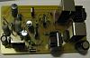
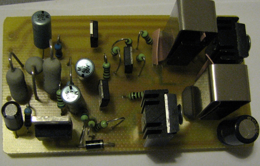
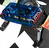
Yes, the solution is (as most solutions) fairly simple once you have it. Here are a couple of pictures of the adapter. On the soldering side you can see the three small transzorbs and also the two surface mount pmoses.
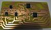
Please neglect the weird cooling solution I have on the right hand side. I replaced the small transistors later with to220-style-ones (the ones that are in the schematic I think) that were easier to apply heat sinks to.
I'm also attaching somebody elses sketch of how the wirings go in the lci lights (to help connecting the right outputs to the right places).
I don't remember the part number of the BMW cable kit but it's somewhere on this forum and shouldn't cost more than around € 25.
Last but not least, I'm attaching the pdf of the etching pattern for the people who the correct gear to do the etching.
Pattern.pdf
Comments welcome.

Please neglect the weird cooling solution I have on the right hand side. I replaced the small transistors later with to220-style-ones (the ones that are in the schematic I think) that were easier to apply heat sinks to.


I'm also attaching somebody elses sketch of how the wirings go in the lci lights (to help connecting the right outputs to the right places).

I don't remember the part number of the BMW cable kit but it's somewhere on this forum and shouldn't cost more than around € 25.
Last but not least, I'm attaching the pdf of the etching pattern for the people who the correct gear to do the etching.
Pattern.pdf
Comments welcome.
Thread Starter
Members
Joined: Aug 2008
Posts: 50
Likes: 0
From: UK
My Ride: Had: 530D 170kW Black 6MT
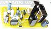
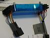
A couple more:
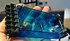
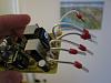
Project (almost) finished. Notice how I lifted the cover of the box with some screw supports (or whatever they are called) to allow better exchange of heat. The boxes are made of polycarbonate, which is a very heat durable material, by the way.


Project (almost) finished. Notice how I lifted the cover of the box with some screw supports (or whatever they are called) to allow better exchange of heat. The boxes are made of polycarbonate, which is a very heat durable material, by the way.


Members
Joined: Sep 2009
Posts: 4
Likes: 0
Hi Mja,
Thanks for all the diagrams and pictures. Can i trouble you to give the p/n for the list of components for this project? I'm having problem selecting the correct parts via RS online, a few options came up for some of the parts, ie. R5 100k, 4.7u etc. Thanks again for putting all these up.
Ryan
Thanks for all the diagrams and pictures. Can i trouble you to give the p/n for the list of components for this project? I'm having problem selecting the correct parts via RS online, a few options came up for some of the parts, ie. R5 100k, 4.7u etc. Thanks again for putting all these up.
Ryan
Thread Starter
Members
Joined: Aug 2008
Posts: 50
Likes: 0
From: UK
My Ride: Had: 530D 170kW Black 6MT
Originally Posted by Peppermintloft' post='1016663' date='Sep 25 2009, 02:13 PM
Hi Mja,
Thanks for all the diagrams and pictures. Can i trouble you to give the p/n for the list of components for this project? I'm having problem selecting the correct parts via RS online, a few options came up for some of the parts, ie. R5 100k, 4.7u etc. Thanks again for putting all these up.
Ryan
Thanks for all the diagrams and pictures. Can i trouble you to give the p/n for the list of components for this project? I'm having problem selecting the correct parts via RS online, a few options came up for some of the parts, ie. R5 100k, 4.7u etc. Thanks again for putting all these up.
Ryan
Members
Joined: Sep 2009
Posts: 4
Likes: 0
Originally Posted by mja' post='1016703' date='Sep 25 2009, 09:58 PM
For the capacitors choose ones that can withstand more than 20 volts (you can see 50V in the pictures) and can safely operate in normal outside temperatures and up to some 100 degrees Celsius (worst case). For the resistors in the kilo-Ohm range just take some cheap 0.25 W or 0.5 W ones. The ~100 Ohm resistors should be able to withstand some 3-5 Watts.
Thread Starter
Members
Joined: Aug 2008
Posts: 50
Likes: 0
From: UK
My Ride: Had: 530D 170kW Black 6MT
Originally Posted by Peppermintloft' post='1016807' date='Sep 25 2009, 06:04 PM
What about those resistors with the ?R ones, how should i select those?
I'll write a brief description of what's the logic behind the circuit later this weekend (now I'm off to Berlin).
Contributors
Joined: May 2009
Posts: 318
Likes: 0
From: North Jersey
My Ride: 2006 M5
Originally Posted by mja' post='1015986' date='Sep 24 2009, 02:40 PM
A couple more:
Attachment 90852
Attachment 90853
Project (almost) finished. Notice how I lifted the cover of the box with some screw supports (or whatever they are called) to allow better exchange of heat. The boxes are made of polycarbonate, which is a very heat durable material, by the way.
Attachment 90854
Attachment 90852
Attachment 90853
Project (almost) finished. Notice how I lifted the cover of the box with some screw supports (or whatever they are called) to allow better exchange of heat. The boxes are made of polycarbonate, which is a very heat durable material, by the way.
Attachment 90854
I'm not saying it works, but it's the principle in sharing the knowledge that was generated on the forum.
It's a shame someone has made money off of so many members when in reality, it was the members who made those original cables (it should be called the e60 cables)... and then all of a sudden... ((BOOOOM))... they decided to keep it a secret and wanted to use PM's on what seemed to be a member driven project. There are some greedy members on here and it's a real shame.
MJA, this is a step in the right direction and thank you for sharing the wealth of knowledge you've gathered from fellow members and the details that go along with it.
For those of you who want to be able to read the schematic provided by MJA you should download the free version of Eagle here: http://www.cadsoft.de/download.htm
Once you have opened the drawings, you can purchase your own components for FRACTIONS of what members are selling the retrofit cable from Newark Electronics (and I mean pennies) : http://www.newark.com
You can go to your local Radio Shack for resistors and capacitors.
This forum is a place that members should be able to come and read, learn and share information. We are all here for the love of the car as so many other members have stated... if you want to be robbed blind by other members so be it, but I honestly don't see myself forking over $300-$500 US for a set of cables that are only worth $50 (if that)...
Once again, thanks for sharing MJA, your a class act.