
550i Project Journal


Thread Starter
Senior Members
Joined: Apr 2009
Posts: 1,122
Likes: 3
From: Seattle
- O2 Bungs are now welded up on the collector for each header
- Sensor modules are installed (3 underneath drivers side cabin filter & 2 underneath dash)
- Killer Chiller mounted to the underside of the front bumper carrier on the drivers side just front of the washer fluid reservoir
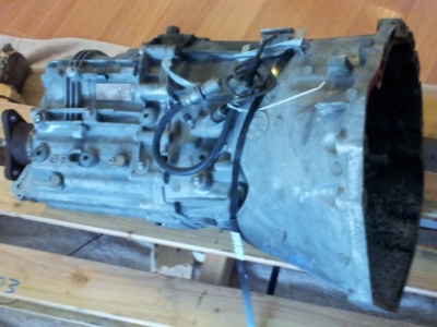
In other news, the GS6-53BZ showed up earlier today. This item was hard to find. 44k miles on it..
Ended up at the shop to witness a 600rwhp e36 m3 get tuned for larger injectors. The 550i happened to be up on the lift, so snapped a couple photos of the Killer Chiller in its new home. More cell phone pics:
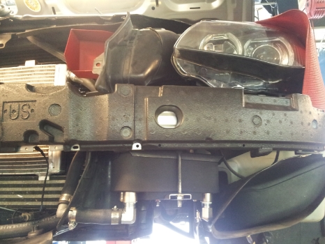
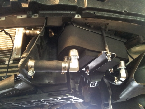
As can be seen from the photos, the coolant lines are routed through the Killer Chiller and we're now waiting on parts so the A/C can be routed through the Killer Chiller as well. The A/C hose clamps that were shipped with the kit aren't of the correct diameter/size for a BMW A/C system. Makes sense given the kit wasn't designed for a BMW to begin with. Currently, the coolant loop looks like this:
Pump --> Heat Exchanger --> Killer Chiller --> Aftercooler --> Pump
Last edited by west; Aug 8, 2013 at 09:18 AM.
Thread Starter
Senior Members
Joined: Apr 2009
Posts: 1,122
Likes: 3
From: Seattle
The KillerChiller appears to be working. Went for a short drive yesterday and the coolant temps are quite cold. Removed the coolant cap after a drive while the car was running and stuck a finger in the coolant reservoir and it felt like a cold beer. This would not be possible with the standard heat exchanger configuration that ships with the ESS supercharger kit. Figure if we insulate the coolant lines and use a larger reservoir then it might be so cold that it will numb your fingers if you keep them sitting in the coolant long enough. This should minimize heat soak or at least cool the intake temps back below/around ambient in a matter of seconds after a hard WOT pull.
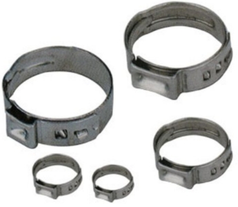
To make the Killer Chiller work on our cars, get the universal kit and ask for A/C hose clamps that are 1" to 1 1/8" closed diameter. Standard hose clamps will not work. The ones you want to use look like this:
To make the Killer Chiller work on our cars, get the universal kit and ask for A/C hose clamps that are 1" to 1 1/8" closed diameter. Standard hose clamps will not work. The ones you want to use look like this:
Last edited by west; Jun 19, 2013 at 08:49 PM.
Thread Starter
Senior Members
Joined: Apr 2009
Posts: 1,122
Likes: 3
From: Seattle
OK, so here's the deal. Manual transmission 545/550's have a 2.93:1 rear differential with a 94mm input CV. The Automatic 545/550's have a 3.38:1 rear differential with a 86mm input CV. The Manual transmission 545/550's have a drive shaft 1617mm in length. The Auto transmission 545/550's have a drive shaft 1615 in length. There is no drive shaft available to run a 3.38 differential with a manual transmission on the 545/550. You have to make one. Before we get in to that. Here are a few photos:
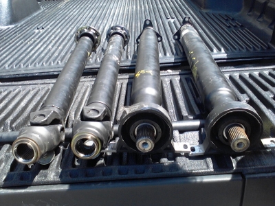
This is a photo of the rear diff input CV's (manual on right/auto on left):
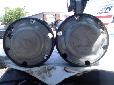
Another photo from the top so you can see the difference in depth as well:
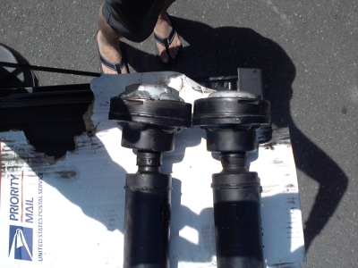
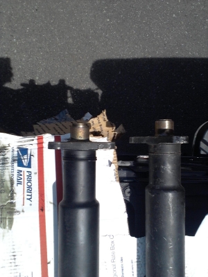
Here is a photo of the front shaft lengths (manual on right/auto on left):
Rear shafts are the same length on manual and auto setup's and as a result the center bearing will be at the same location:
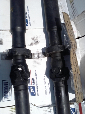
Fortunately you can make a hybrid drive shaft by taking the front shaft from a manual transmission and a back shaft from an automatic and mate them together. Use a wrench to take the shafts apart by loosening the bolt just rearward of the center u-joint as seen here:
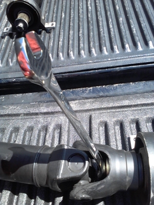
Once the drive shafts are taken apart, you can see that the center splines are the same on the auto and manual drive shafts. This is a good thing because the CV splines on the backs shaft are different!
The next step would be to bolt the front half of the manual transmission drive shaft to the back shaft of the auto transmission drive shaft and take the hybrid to a shop and have it balanced.
This is a photo of the rear diff input CV's (manual on right/auto on left):
Another photo from the top so you can see the difference in depth as well:
Here is a photo of the front shaft lengths (manual on right/auto on left):
Rear shafts are the same length on manual and auto setup's and as a result the center bearing will be at the same location:
Fortunately you can make a hybrid drive shaft by taking the front shaft from a manual transmission and a back shaft from an automatic and mate them together. Use a wrench to take the shafts apart by loosening the bolt just rearward of the center u-joint as seen here:
Once the drive shafts are taken apart, you can see that the center splines are the same on the auto and manual drive shafts. This is a good thing because the CV splines on the backs shaft are different!
The next step would be to bolt the front half of the manual transmission drive shaft to the back shaft of the auto transmission drive shaft and take the hybrid to a shop and have it balanced.
Last edited by west; Jun 5, 2013 at 03:16 PM.
Thread Starter
Senior Members
Joined: Apr 2009
Posts: 1,122
Likes: 3
From: Seattle
Another update with a few photos..
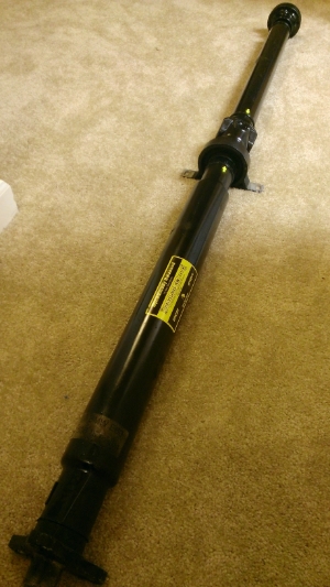
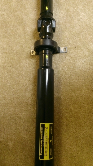
Took the hybrid driveshaft to Drivelines Northwest. They worked their magic and returned the item with their stamp of approval:
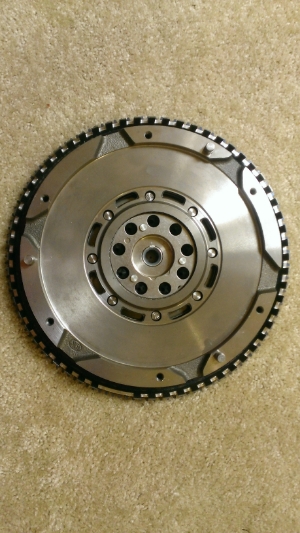
Dinan lightweight clutch and flywheel showed up too! The box was pretty mangled when it arrived and the pieces (flywheel,pressure-plate,clutch) were floating in the box clanking on each other. The pressure plate got a little banged up on the outer edge of the face that makes contact with the clutch and there are some light scratches on the face. Not sure if the dings (between 8 and 9 o-clock in the first image below) along the outer edge of the pressure plate face will cause problems:
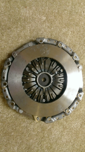
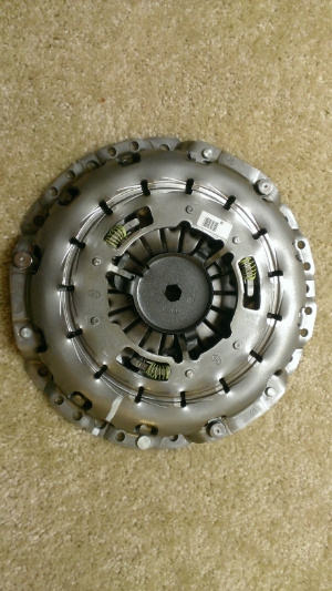
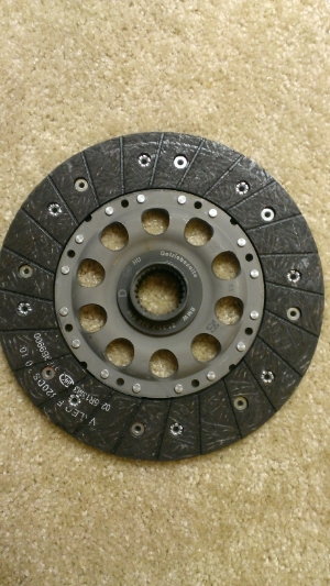
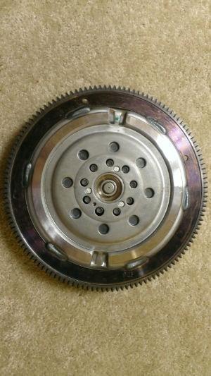
Does anyone know if the clutch is a lightened factory unit? I was told by the Dinan sales guy that the clutch was designed and built from the ground up by Dinan. Looks like a lightened factory unit to me though.
Took the hybrid driveshaft to Drivelines Northwest. They worked their magic and returned the item with their stamp of approval:
Dinan lightweight clutch and flywheel showed up too! The box was pretty mangled when it arrived and the pieces (flywheel,pressure-plate,clutch) were floating in the box clanking on each other. The pressure plate got a little banged up on the outer edge of the face that makes contact with the clutch and there are some light scratches on the face. Not sure if the dings (between 8 and 9 o-clock in the first image below) along the outer edge of the pressure plate face will cause problems:
Does anyone know if the clutch is a lightened factory unit? I was told by the Dinan sales guy that the clutch was designed and built from the ground up by Dinan. Looks like a lightened factory unit to me though.


New Members
Joined: Jun 2012
Posts: 94
Likes: 0
From: Charlotte, NC
My Ride: M5 SMG
Model Year: 2006
Great post! I am swapping a differential from an automatic into my manual 545i for a cheap upgrade. I ordered the automatic drive shaft yesterday as they are easy to find. Thanks.
Thread Starter
Senior Members
Joined: Apr 2009
Posts: 1,122
Likes: 3
From: Seattle
UPDATE: been running the car on factory fuel pump, 100% 101 unleaded, shorter pulley, and killer chiller the past 600 miles or so. the thing runs like a raped ape. gauges are seeing afr's of roughly 12.0 at 6300+rpm at 8.5 psi with no catalytics. surprised the engine hasn't blown up yet. the power is unreal. seems to be holding together for now at least. auto tranny hasn't popped yet which i find sort of odd after speaking with ess beforehand but whatever. i'm sure it will pop eventually. had the brakes painted so we could remove the brembo logos from the brakes. they look great. mounted the gauges ghetto style underneath the left drivers vent. will try and get a video here in the next few days. oh, plx gauges don't talk to this car. the obdii stuff is broken. what a rip off. don't buy these gauges unless you intend on running your own sensor modules.
Last edited by west; Aug 8, 2013 at 01:09 AM.

Thread Starter
Senior Members
Joined: Apr 2009
Posts: 1,122
Likes: 3
From: Seattle
the displays are capable of displaying data from sensor modules if you purchase them. The display module is incapable of talking obdii with the car...which is supposed to be a built-in feature of the obdii-capable plx gauges. Waste of money getting these if you expect the obdii data (rpm, speed, temps,.etc) . These obdii display packages simply do not work on this car.
UPDATE: planning to put the drive train under the knife soon. If anyone in the Seattle area has a transmiasion jack and engine support beam that they are willing to part with temporarily please let me know.
UPDATE: planning to put the drive train under the knife soon. If anyone in the Seattle area has a transmiasion jack and engine support beam that they are willing to part with temporarily please let me know.
Last edited by west; Aug 11, 2013 at 02:20 PM.
Thread Starter
Senior Members
Joined: Apr 2009
Posts: 1,122
Likes: 3
From: Seattle
Began building blocks for the car to stand on while working underneath it. Also cleaned up the transmission a bit. Looks like the output shaft coupler is of the wrong size (BMW issues two sizes). Need to eventually get one that will suit the job.
Took a short video of the gauges doing their thing. Not a very practical example, but the video demonstrates how I just stuck the gauges to the dash above the drivers side vent using double-sided 3M black sticky tape as well as the left display toggling between boost or air/fuel (this is done with controls that are tucked under the steering column). Not sure why the variance in air/fuel between the left and right banks in this video but when it's on the road they are both pretty much the same.
Took a short video of the gauges doing their thing. Not a very practical example, but the video demonstrates how I just stuck the gauges to the dash above the drivers side vent using double-sided 3M black sticky tape as well as the left display toggling between boost or air/fuel (this is done with controls that are tucked under the steering column). Not sure why the variance in air/fuel between the left and right banks in this video but when it's on the road they are both pretty much the same.
Last edited by west; Aug 13, 2013 at 07:54 PM.