An LCI tail light adapter schematic for pre-facelift e60
 09-30-2009, 05:00 AM
#11
Members
Thread Starter

Join Date: Aug 2008
Location: UK
Posts: 50
Likes: 0
Received 0 Likes
on
0 Posts
My Ride: Had: 530D 170kW Black 6MT
OK folks, here goes
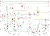
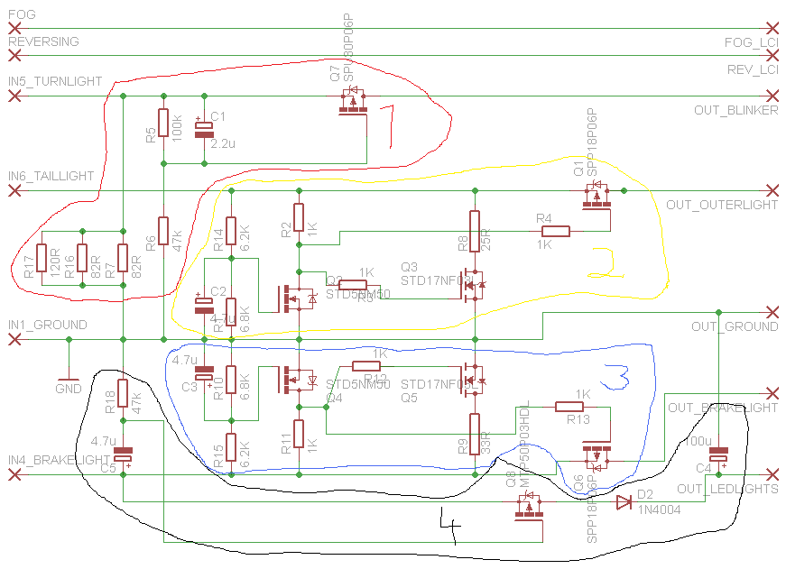
In the schematic you can see 4 subcircuits circled. Subcircuits 2 and 3 are, at a closer inspection, actually almost identical (except for R8 and R9). Note well that the transistors in the circuit are _not_ used as amplifiers, but as digital switches, i.e. we want them to conduct no current at all (having all the voltage over them) or alternatively as much as possible (with as little voltage over them as possible). Remember also that with mosfets there is ~no current to or from the Gate and that we are using enhancement mode FETs (see wikipedia). One more important obsevation is that the car only outputs 12 Volts to the lights. Sometimes it's a full 12V and sometimes it's chopped (so will look less then 12 V on a DC-voltmeter).
-------------------------------------------------------------
-------------------------------------------------------------
1. The point of this circuit is to replace the bulb based blinker with the led based blinker in the LCI lights. Resistors R7, R16 and R17 are needed to fool the car's electronics, otherwise a faulty bulb error message occurs. If you do get an error message that a blinker is out, replace R17 with a smaller one, i.e. 100 Ohm or 82 Ohm.
The first lesson here is that the transistor Q7 is a p-channel mosfet (like many others in the design, i.e. Q1, Q6, Q7 and Q8 - Q2, Q3, Q4 and Q5 are n-channel mosfets). The reason we need to use pmos:es is that the load (leds / bulb / whatever) must be connected to the Drain of a mosfet (the kind of lonely terminal in the schematic) for proper operation. As we physically cannot have the bulbs and leds between the input voltage and the transistor (as would be needed for n channel mosfets), we must use p-mosfets as drivers. In other words, in the design all pmoses have their Drain pointing to the load and Source pointing towards the input voltages (IN4, IN5, IN6) and thus the gate-source voltages are negative (if you replace any pmos with an nmos the design fails as nmos:es are controlled by positive gate-source voltages).
As is widely known, the car sends check voltages to the blinkers. The bulbs are too slow to blink, but the leds are way faster and without the circuit one would get blinks every now and then, during start up and also during driving. The purpose of R5, R6, C1 and Q7 is to filter out the very short blinks but pass through the ordinary blinking cycle. The problem is, the switch-on-voltage (called the threshold voltage, Vth) of mosfets are highly variable even for transistors of the same type. The data sheet of the transistor will tell an interval in which the Vth can vary (for some 99.9999% of transistors or so). Thus, all the circuits are a comporomise between robustness and reaction time. Resistors R5 and R6 form a voltage divider (we want the Gate of the fet to operate in a sort of sweet spot) and R6 and C1 form an "inverse" low pass filter, i.e. you must view it from Ground to IN5, not from IN5 to Ground, as the Gate of the pmos transistor is controlled by a negative voltage. Now, with the quick peaks of 12 volts, the voltage over C1 (which is also the same as the gate-source voltage, Vgs) will not reach the Vth of Q7 and thus there can be no current through Q7 and no blinking. When IN5 stays at 12 volts for a bit longer (in the normal blinker cycle) the Vgs soon reaches Vth and Q7 starts to pass current to the blinkers.
Effectively we filter out the short blinks and also cut a bit off of the normal blinking cycle. Lowering the capacitance of C1 will make the circuit faster but will also risk showing the quick check blinks.
-------------------------------------------------------------
2. & 3. The voltage levels for the inputs (IN6 and IN4) are: 0 Volts (don't care), very quick 12 V peaks for checking the bulbs (which we want to filter out), chopped 12 V for dimly lit bulbs in pre-LCI (about 3.3 ms of 12 V and about 9.3 ms of 0 V repeated, thanks to the unknown guy who had an oscilloscope) and full 12 V (when braking).
The first part (R1, R14, C2) of subcircuit 2 forms a low pass filter (R14 and C2) and a voltage divider (R1 and R14).
Case 2.1: When IN6 is 0 V, peaking 12 V or the chopped 12 V, the voltage over C2, i.e. also the Vgs of Q2, never reaches the threshold voltage region of Q2 and Q2 is thus off (I simulated this in ltSpice under quite different scenarios and worst cases).
When Q2 is off (not conducting), there is no current through R2 (remember that there is no current to the Gates of Q1 and Q3 but the resistors R4 and R3 are there for emergencies, i.e. if something goes very very wrong) and thus no voltage drop over R2. This means that the Gate of Q1 follows IN6 and Vgs of Q1 will be 0 Volts (regardless of IN6) -> no current to the bulbs. On the other hand, the gate of Q3 will also be following IN6 and when IN6 is high (12V), the Vgs of Q3 will be 12V (Q3 is an nmos and its Source is connected to Ground) and there will be full current, limited by R8, through Q3 (making the car think everything is alright and giving the LCI effect of no bulbs shining).
Case 2.2: When hitting the brake pedal IN6 (EDIT: Sorry, this only happens in the emergency brake situation with IN6, if enabled! Consider in your mind replacing IN6 with IN4, the operation is the same) will go to full 12 V. Slowly (relatively speaking, in some 100 ms maybe) the voltage over C2 (i.e. Vgs of Q2) will reach the Vth of Q2. Now when this happens, current will start to pass through R2 and R2 will soon reach almost 12 Volts (with the Q2 fully on the voltage over it will be almost 0 V). In this scenario Q3 will go/stay off since its Gate is almost at 0 V. At the same time the gate of Q1 will be close to zero and Vgs of Q1 will be almost -12 V. The Q1 starts to pass current and will lover its Source-Drain voltage to almost 0 to pass as much current as possible (limited by the resistance of the bulb it is driving). Thus, brakes work
Now R8 is marked as 25 Ohms, but may need to be lower, at around 20R or 18R (depending on the software of the car possibly) and R9 might be something like 30R.
NOTE WELL: Q1, Q6, R8 and R9 _must_ have heat sinks as significant currents will go through them!
-------------------------------------------------------------
4. Subcircuit 4 (LED rod circuit) is connected to IN4 (as is subcircuit 3) but is parallel to subcircuit 3 and thus they don't really affect each other too much. On a practical note, subcircuit 4 could also be connected to IN6 and when keeping lights off and hitting brakes, the led rods wouldn't switch on. However, this disables the rest light function (when the car is switched off it's possible to have the angel eyes and back led rods switched on).
When I was looking for the pmos for the subcircuit 4 it turned out to be quite difficult to find one with the threshold voltage interval between 1 and 2 volts. The one I found (MTP5..) is quite expensive at around 3-4 euros each. Why does it need to be between 1 and 2 volts? Because the led rods are supposed to be switched on during the chopped 12 V cycle (as well as the full 12 V, but that's the easy part). If we also want to filter out the quick blinks at ignition, we need a low pass filter once again (C5 and R18). The problem is, to filter out the blinks we need to choose C5 quite big, effectively the low pass filter quite slow, and thus the the voltage over C5 (which once again is the same as Vgs of Q8) will never quite exceed the mean of the input (which is approximately a bit more than 12V / 4 = 3 V) under the chopped voltage. To sum up, it takes quite many cycles of the chopped voltage for C5 to reach the threshold voltage (Vth) of Q8. When it does, Q8 starts to pass current to the led rods. It also charges the C4 to 12 Volts and during the OFF state of the chopper, the C4 will unload it's charge to the led rods (and D2 prevents C4 from unloading back to R10, R11 and the other guys), thus providing quite a good intensity.
-------------------------------------------------------------
That's all for now, thanks for listening! Any mistakes I made, comments, etc just shout!
 09-30-2009, 06:13 AM
#12
Members

Join Date: Nov 2008
Location: Norcal
Posts: 112
Likes: 0
Received 0 Likes
on
0 Posts
Originally Posted by 545ier' post='1020730' date='Sep 29 2009, 09:50 PM
Congrats on this fine DIY.
09-30-2009, 07:06 AM
#13
Contributors
Join Date: Apr 2008
Location: Houston,TX
Posts: 3,573
Likes: 0
Received 0 Likes
on
0 Posts
My Ride: Original E60 Spec:
530i - Silver Grey Out, Black Dakota Leather In, Navigation Pro, Voice Command, HiFi Audio, Sports Package, Premium Package, Cold Weather Package w/ Heated Seats, Style# 123 Alloy Track Wheels, Auto AC, Power Front Seats, Active Turn Xennon Headlights,
Mods:
OEM M-Tech Front Bumper, OEM M Side Skirts, OEM M5 Rear Bumper, M5 Trunk Lid Finisher, M5 Style Mirrors, Custom Hamann Style Splitter, Custom Hartge Style Diffuser, RD Sport Boot Spoiler, LCI Taillights, Bruce Miranda's V4 LCI Retro Cables, 6000K Xenon light Bulbs, Xenon White LED License Plate Lights, 8000K HID 9006 Fog Lights, Akalius� Front Headlight Euro Overlays, Matte Black Kidney Grilles, E60.Net Clings, Debadged, Llumar Tinting "Micro Edged, 15% Rear 35% Sides,
Engine Mods:
Custom Magnaflow Quad Exhaust w/ Eisenmann Stamped 3� Tips, RPI Scoop (Red)
Added Electronics:
V1 Equipped (Hardwired), OEM Alpine CD Changer Retrofit,
Shoes:
SOLD-20" Staggered Vertini Hennesey Rims, Falcon 452's Tires-SOLD
New Shoes:
19" VMR 710 Hyper Silver, General Exclaim UHP 245/35/19 Front-275/30/19 Rear, Gloss Silver Caliper Paint Job DIY
^_____________
Retired
______________
Took Delivery 10/26/2009: LOADED! E60 M5 Silverstone II/Black, Active Seats, Comfort Ventilated/Heated Seats, HUD, Brushed Aluminum Trim,
Nice DIY MJA! Thanks for sharing! 
09-30-2009, 08:44 AM
#14
Members
Thread Starter
Join Date: Aug 2008
Location: UK
Posts: 50
Likes: 0
Received 0 Likes
on
0 Posts
My Ride: Had: 530D 170kW Black 6MT
I found myself smiling when I noticed the American cousins thanking me for the community effort and the European guy making remarks about capital and business opportunities. I guess Change is coming after all 
More seriously, if you come up with a BOM I can have a look at it. I can also dig my RS Electronics ordering lists tomorrow for the part names.
More seriously, if you come up with a BOM I can have a look at it. I can also dig my RS Electronics ordering lists tomorrow for the part names.
09-30-2009, 05:17 PM
#15
Contributors
Join Date: May 2009
Location: North Jersey
Posts: 318
Likes: 0
Received 0 Likes
on
0 Posts
My Ride: 2006 M5
Attached is a BOM for the components based off of the schematic. Pricing is based on the qty purchased, minimum order & availability.
Revise, edit and re-post...
Revise, edit and re-post...
10-01-2009, 02:24 AM
#16
Members
Thread Starter
Join Date: Aug 2008
Location: UK
Posts: 50
Likes: 0
Received 0 Likes
on
0 Posts
My Ride: Had: 530D 170kW Black 6MT
Originally Posted by 545ier' post='1021669' date='Oct 1 2009, 03:17 AM
Attached is a BOM for the components based off of the schematic. Pricing is based on the qty purchased, minimum order & availability.
Revise, edit and re-post...
Revise, edit and re-post...
- R5 is 100 and should be 100k
- the one you chose for R8 is not advisable, see my changes below
- R9 should be 33 ohms, not 33k. Or actually, use the same component for R8 and R9 to start with. So get two 30W 25 ohm resistors for R8 and R9.
- power rating for R17 is only 1W. I'd take the same 5W as for R7 and R16. Also consider ordering 100 ohm resistors, just in case you get a blinker error.
- Q2 and Q4 must be IPAK, not DPAK (which is surface mount), if you want to use my pcb design. Q3 and Q5 are correct, i.e. in my pcb they should be DPAKs.
- Q7: for Q7 you can also use Q1/Q6 and thus you can order all your parts from Newark. The SPU would be in a slightly more compact package but if ordering it is difficult, replace by Q1 (they have the same gate threshold voltage properties, which is important).
Thus I'd make the following changes (please verify):
R5: http://www.newark.com/vishay-dale/ccf07100...tors/dp/71M0991
R8: http://www.newark.com/caddock/mp930-25-0-1...stor/dp/02H2385 _or_ http://www.newark.com/bourns/pwr221-2fc25r...stor/dp/64M0649
R9: The same as R8 or you can try http://www.newark.com/ohmite/tbh25p30r0je/...stor/dp/66K6888
R17: http://www.newark.com/welwyn/wp4s-120rja2/...tors/dp/05M1907
Q2 & Q4: http://www.newark.com/stmicroelectronics/s...-pak/dp/26M3523 <- these I-PAK:s should work as a replacement
Q7: http://www.newark.com/infineon/spp18p06p/_...9?Ntt=SPP18P06P (the same as Q1/Q6)
Besides you may want to get some cooling, the transzorbs, polycarbonate cases and ferrite rings:
Ferrite snap on: http://www.newark.com/fair-rite/0443167251...ds_PrivateLabel
Transzorbs: http://www.newark.com/vishay-general-semic...iode/dp/05R5762
Heatsinks: This is a problem as space is tight on the pcb. The ones I used are not available in Newark, or I was unable to find them (http://de.rs-online.com/web/search/s...uct&R=189-8303). Maybe this would do, with modifications: http://www.newark.com/aavid-thermalloy/577...t=577002B00000G
Polycarbonate case: http://www.newark.com/hammond/1591atbu/mul...ures/dp/84C9912
In addition I think the OEM part number for the BMW cables that are needed is: 61120432110
10-01-2009, 06:06 AM
#17
Senior Members
Join Date: Nov 2008
Location: Houston, TX
Posts: 670
Likes: 0
Received 0 Likes
on
0 Posts
My Ride: 2006 530i, Jet Black, Tan, Premium, Steptronic
Originally Posted by 545ier' post='1020730' date='Sep 29 2009, 11:50 PM
Congrats on this fine DIY. Someone who isn't out to rob us blind and someone who doesn't mind sharing details such as schematics for a DIY on LCI Cables!
I'm not saying it works, but it's the principle in sharing the knowledge that was generated on the forum.
It's a shame someone has made money off of so many members when in reality, it was the members who made those original cables (it should be called the e60 cables)... and then all of a sudden... ((BOOOOM))... they decided to keep it a secret and wanted to use PM's on what seemed to be a member driven project. There are some greedy members on here and it's a real shame.
MJA, this is a step in the right direction and thank you for sharing the wealth of knowledge you've gathered from fellow members and the details that go along with it.
For those of you who want to be able to read the schematic provided by MJA you should download the free version of Eagle here: http://www.cadsoft.de/download.htm
Once you have opened the drawings, you can purchase your own components for FRACTIONS of what members are selling the retrofit cable from Newark Electronics (and I mean pennies) : http://www.newark.com
You can go to your local Radio Shack for resistors and capacitors.
This forum is a place that members should be able to come and read, learn and share information. We are all here for the love of the car as so many other members have stated... if you want to be robbed blind by other members so be it, but I honestly don't see myself forking over $300-$500 US for a set of cables that are only worth $50 (if that)...
Once again, thanks for sharing MJA, your a class act.
This looks pretty complicated for those of us who are electronically challenged and I'd gladly pay someone to do it for me.
10-01-2009, 07:38 AM
#18
Members
Thread Starter
Join Date: Aug 2008
Location: UK
Posts: 50
Likes: 0
Received 0 Likes
on
0 Posts
My Ride: Had: 530D 170kW Black 6MT
Originally Posted by txag_530i' post='1022031' date='Oct 1 2009, 04:06 PM
Why shouldn't someone make money off research and development? There is a demand for the service, so a smart business person fulfills the demand and makes a few $ or ?. Isn't that what capitalism is all about?
This looks pretty complicated for those of us who are electronically challenged and I'd gladly pay someone to do it for me.
This looks pretty complicated for those of us who are electronically challenged and I'd gladly pay someone to do it for me.
10-01-2009, 08:24 PM
#19
Contributors
Join Date: May 2009
Location: North Jersey
Posts: 318
Likes: 0
Received 0 Likes
on
0 Posts
My Ride: 2006 M5
BOM Revision 2 attached.
I've added other materials needed for the making of the PC board.
- PCB Board
- Muratic Acid
- Hydrogen Peroxide
- Thermal Compound
Along with those components recommended by MJA.
- Ferite Snaps
- Tranzorbs
- Polycarbonate Case
- Heat Sinks
Pricing for the cables and 100 ohm resistors are still needed... I will update once I know.
10-02-2009, 12:54 AM
#20
Members
Thread Starter
Join Date: Aug 2008
Location: UK
Posts: 50
Likes: 0
Received 0 Likes
on
0 Posts
My Ride: Had: 530D 170kW Black 6MT
Looks good. Remember that you need 2 boards but only 1 set of cables from BMW (it comes with cables for both sides). I guess you would additionally need someone with the UV-light station to get the pattern on the PCB, or do more novel and cheaper approaches exist nowadays? Drilling the holes is also quite time consuming without a computer controlled drill (my colleague had one in Finland).