tesrt
 12-28-2013, 03:06 PM
#1
Senior Members
Thread Starter
Join Date: May 2011
Location: San Antonio, TX
Posts: 378
Likes: 0
Received 0 Likes
on
0 Posts
My Ride: 2006 550i sport pak. all the other goodies..
MODS: M5 front, sides, aFe throttle body spacer, RPI Red scoop, amber angle eyes, powder coated sport rims, tinted tail lights. smoked side blinkers, color of car and rims roundels, real carbon fiber roof spoiler, 550i number flat black, LED license plate lights, MTX 12' sub, dyno mat, tinted Windows, flat black grill, flat black exhaust tips, light smoke headlight tint, foged out eyelash, velocity booster.


 03-26-2014, 03:41 PM
#6
Members
Senior Members
Join Date: May 2012
Location: Tampa Bay, FL
Posts: 2,539
Likes: 0
Received 10 Likes
on
6 Posts
My Ride: 530i
Model Year: 2004
Engine: M54
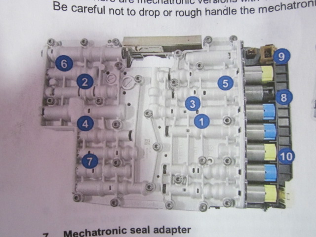
This is a step by step DIY for four different transmission procedures. While this DIY was written specifically for an early production 6HP19, later 6HP19 and 6HP26 procedures should be very similar, if not identical. The four different procedures covered in this DIY are fluid replacement, fluid and transmission pan replacement, Mechatronic sealing sleeve replacement, and solenoid replacement.
If you are simply replacing fluid, the only part you will need is replacement fluid. I would also recommend replacing the drain and fill plugs, as both contain a rubber sealing ring, as well as the oil pan gasket if your pan has never been removed.
If you are replacing the Mechatronic sealing sleeve, you will need all of the aforementioned parts along with a new sealing sleeve.
If you are performing a routine fluid and filter replacement, you will need the service kit offered by the CTSC. The transmission filter has been integrated into the pan by ZF. The pan will come with a new oil pan gasket and drain plug pre-installed.
If you are replacing shift solenoids, you will need seven liters of fluid, shift solenoid kit, the four sealing sleeves (not to be confused with the 'Mechatronic sealing sleeve'), a new Mechatronic sealing sleeve, a new bridge seal, and a new foam solenoid insulator. If your pan/filter assembly has never been changed, you should also buy a new pan, along with a new fill plug.
Before we begin, I'll mention the mandatory disclaimer: By performing any repair to your car outlined in this thread, you assume ALL RESPONSIBILITY for any damage that occurs to you, your equipment, or your car. 100% on you, 0.0% on me. I also cannot guarantee this will solve your specific problems, if there are any present. The only way to guarantee that would be to replace the entire transmission, which is exactly why BMW recommends it. However, these transmissions are repairable, and many transmission faults can be traced to failure in one or more components mentioned in this thread. Use your best judgement and carryout the repair YOU think is best for YOUR car.
This DIY also assumes you are comfortable performing somewhat complex repairs to your car, have access to all necessary tools, and are familiar with using INPA. You will need INPA to measure transmission temperature. If you don't have access to INPA, you will need to find some way to measure and monitor transmission fluid temperature.
Before we dig in I'll give you a little history on my car. I have a March of '04 build 530i, with ZF's 6HP19 automatic transmission. I bought the car with approximately 94,000 miles on it. Before I owned it, it was owned by a middle aged gentlemen who had the car serviced by BMW of Sarasota since new. So basically, my car was never 'abused' that I know of. I started experiencing some erratic shifting, along with error codes that would result in the transmission going into 'failsafe' mode. The codes I retrieved on a regular basis were 4F81 and 4F85, which reference slipping in the A clutch and E clutch of the transmission. After getting 4F85 five or six times, I knew that if I let it go too long I was going to be replacing the transmission, as slipping in the clutches will result in transmission failure. Since replacing the fluid and resetting adaptations didn't resolve the problem, I decided to dive in and replace the shift solenoids, as they are known to fail and cause the types of problems I was having. The shift solenoids are contained in the valve body, which ZF refers to as the 'Mechatronic'. I ordered all of my parts from thectsc.com. They are a great outfit to deal with, and I highly recommend them for any transmission parts needed for any of these procedures.
Before doing anything, you will need to have the car elevated on a lift or jack stands. You need to have it elevated enough to freely work completely underneath the car. If you use jack stands, please be extremely careful. Safety first, everything else is second.
Let's get started...
step 1: Remove center floor covering. The center floor covering is held my multiple fasteners of different sizes. Once all fasteners are removed, the covering will simply drop from the car without using any force.
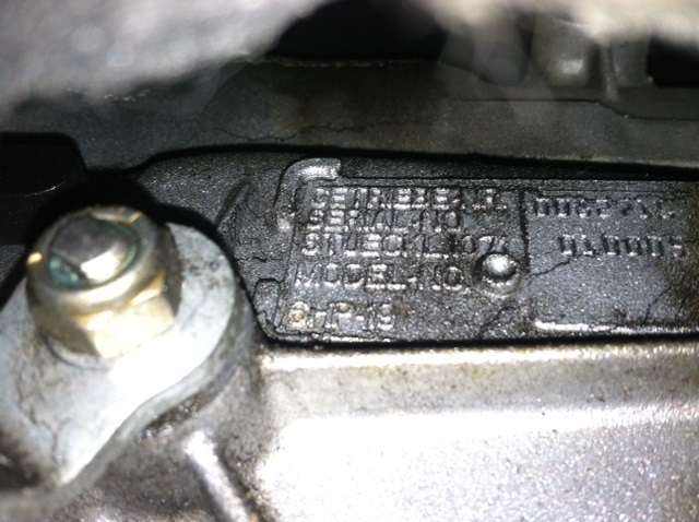
step 2: You will need to identify your transmission by finding the serial number plate. The plate should be on the outside of the casing, near the middle, and on the left side. This serial number is important if you are replacing solenoids and related seals, as they will need to be ordered by using this serial number. Below is a picture of the plate on my car, the number that is of importance is the one that follows the text "STUECKL". My transmission's number is '1071 010005', as you can see in the photo.
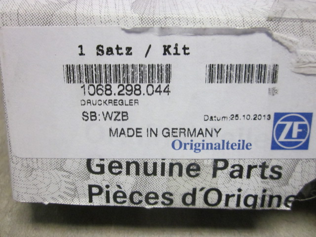
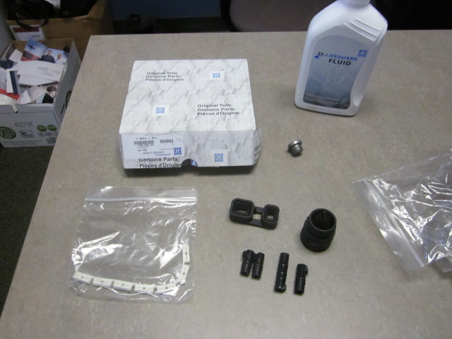
step 3: Order the appropriate parts! I ordered all of mine from thectsc.com. If you need to drive the car for a few days without the floor coverings installed, be mindful of the fact that they are not there to protect your undercarriage. thectsc.com ships quickly, so you shouldn't be wating long. Once parts arrive, you are ready to proceed. Below is a picture of the parts I used for solenoid replacement, including the part number for the solenoid set that applies to my early build 6HP19.
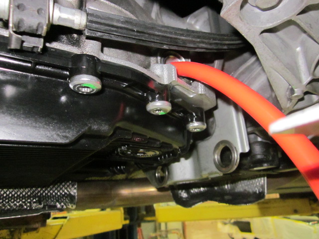
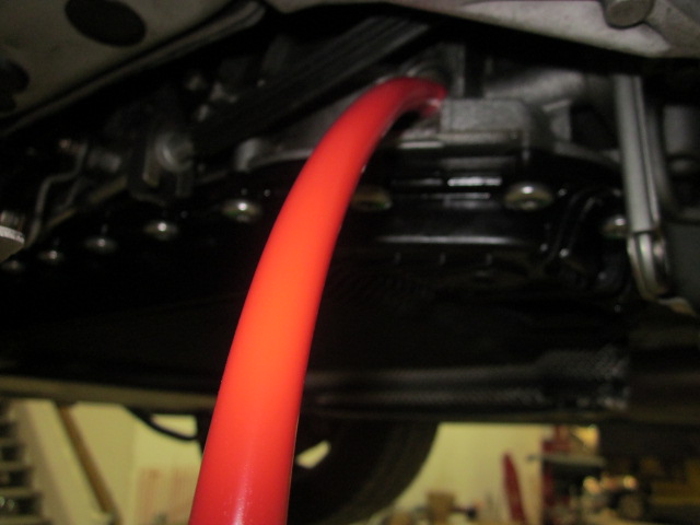
step 4: remove transmission FILL plug. I always remove the fill plug first, because I never want to find myself in a situation where I've drained all of the fluids out of a component with no way to get new fluids back in. Yes, it has been known to happen. I highly recommend removing the fill plug first. Below is picture showing the location of the fill plug (orange tube is inserted in this picture) relative to the drain plug. The fill plug is on the left side, towards the rear. an 8mm allen wrench works best to remove it.
step 5: undo drain plug on transmission pan, drain transmission fluid into a clean drain pan. You will want to use a clean pan as the fluid should be recovered and set aside until all service is complete, as this drained fluid can be helpful if you run out of new fluid during any of these processes. While reusing old fluid is less than ideal, it is certainly better than running out completely. I used a plastic cat litter pan that held all of the drained fluid without running over. It was less that $6 and works great. Drain plug has been removed in this photo.
step 6: Allow the transmission fluid to fully drain. If you are simply replacing the transmission fluid, reinstall the drain plug and skip to step 30.
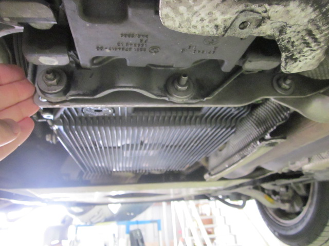
step 7: unbolt and remove the center exhaust system bracket. The bracket will need to be removed in order to fully access the transmission pan mounting screws at the rear of the pan.
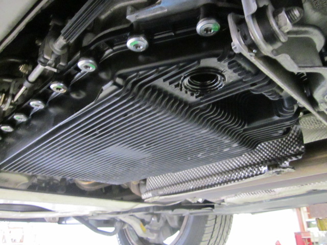
step 8: Remove all transmission pan retaining screws, then lower the transmission pan from the car. Be careful when lowering the pan, as there will still be a small amount of standing fluid in the pan. You can see from this photo why we need to remove the exhaust bracket. If you are performing a routine fluid and pan/filter replacement, skip to step 29.
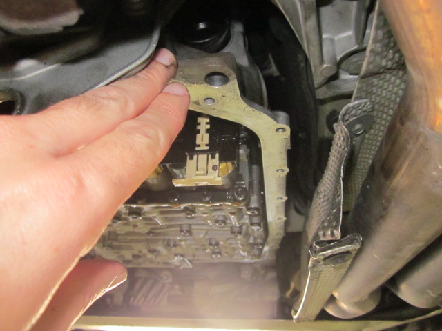
step 9: Unlock Mechatronic sealing sleeve by pulling down on unlocking lever. The sleeve is 'locked' into position by this lever. Unlocking the lever should NOT take much force at all. I was able to unlock it by gently pulling down with two fingers.
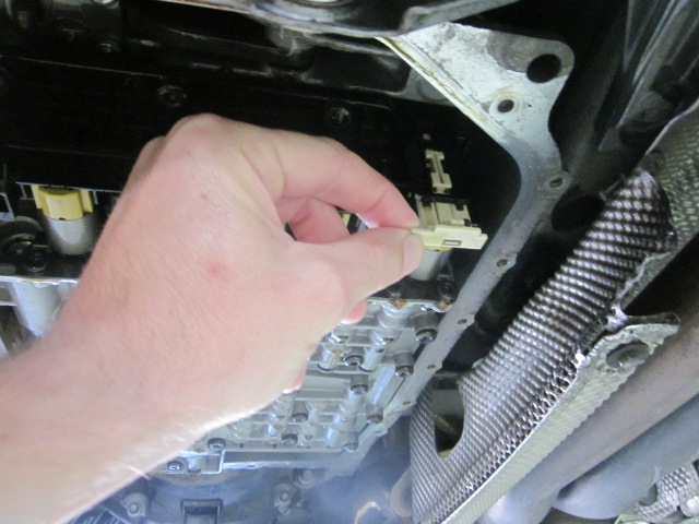
step 10: disconnect wiring harness connector at the Mechatronic sleeve. If you look at the connector, you will see a square tab at about the 5 o'clock position. I used a 1" wooden dowel to undo the connector. Place either a finger, dowel, or any other appropriate tool on the tab. The connector will unscrew by rotating it in a COUNTER-CLOCKWISE motion. Once the connector is fully unseated, push it up and out of the way to fully expose the Mechatronic sealing sleeve.
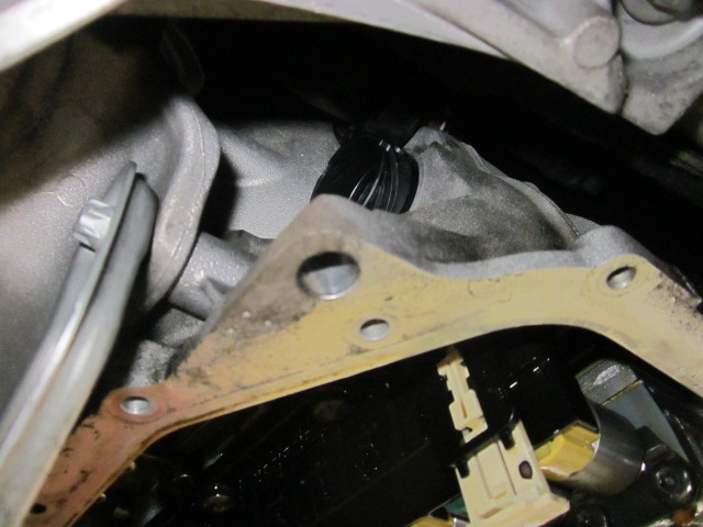
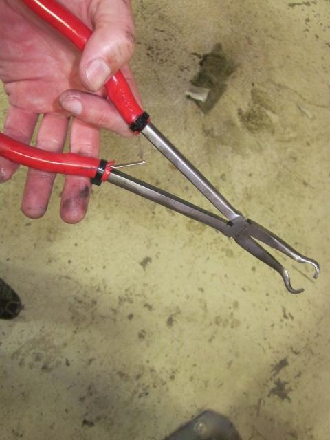
step 11: remove Mechatronic sealing sleeve. The mechatronic sleeve can be removed by gently rocking the sleeve from side to side while pulling it outward, either by hand or with a set of pliers. There is only a very small amount of room between the transmission and the transmission bracket, so unless you have really small hands a set of pliers similar to what I used is probably going to be the best route. These are the pliers I used, as they allowed me to get good clamping force on the sleeve while extracting it. DO NOT attempt to remove the sleeve with a twisting motion, as you risk cracking the locating tab that is molded into the Mechatronic connection point. Here you can see the sleeve relative to the locking lever, as well as the limited amount of work area you'll be dealing with. If you are only replacing the Mechatronic sealing sleeve located on the outside of the transmission, skip to step 26.
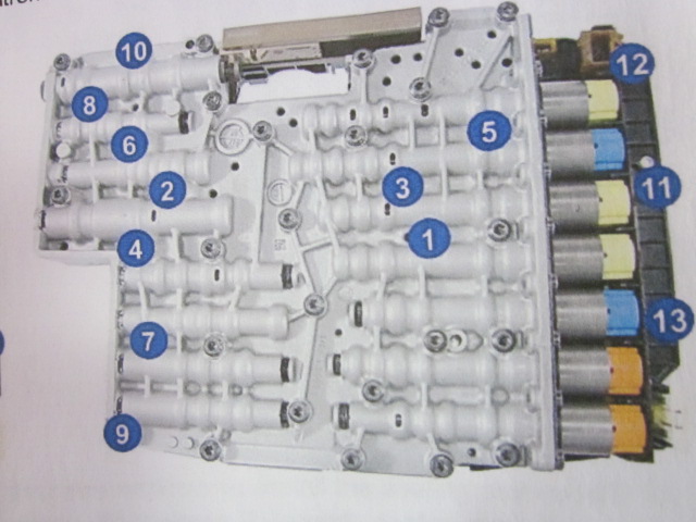
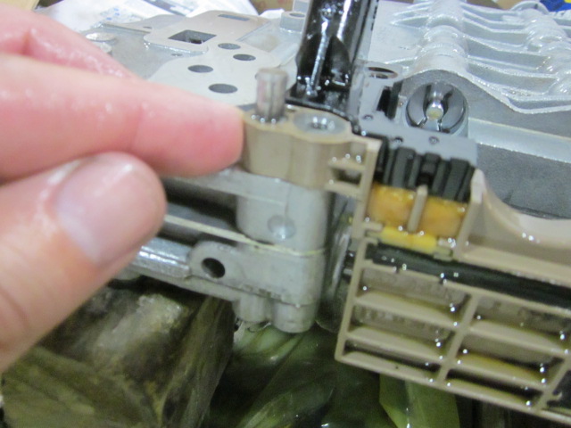
step 12: unbolt Mechatronic mounting bolts. It is very important to support the Mechatronic while you are unbolting it from the transmission. If you don't have it supported, it WILL fall on the ground, likely break, and put a $1700 dent in your wallet. It is also vital that any time you are handling the Mechatronic you do NOT allow anything to come into contact with the pins in the electrical connector. Any static electricity that is discharged into the pins will likely destroy the TCM and require replacement. Take your time and be careful!! Below are two diagrams showing the bolt pattern for the Mechatronic. Compare the stampings in yours, and remove the appropriate bolts while supporting the Mechatronic.
step 13: Carefully lower Mechatronic from transmission, and place on a clean working surface. I used a workbench with two blocks of 2x4 to support the Mechatronic while I worked with it.
step 14: remove mounting bolts securing TCM to the Mechatronic. The TCM is the computer portion of the Mechatronic, encased in black plastic. The bolts that hold the TCM to the Mechatronic are the same size as the ones that hold the two aluminum halves of the Mechatronic together. It is very important to only remove the bolts that are holding the TCM in place. By turning the mechatronic over and following the bolts from one side to the other, it should become apparent which bolts are for the TCM.
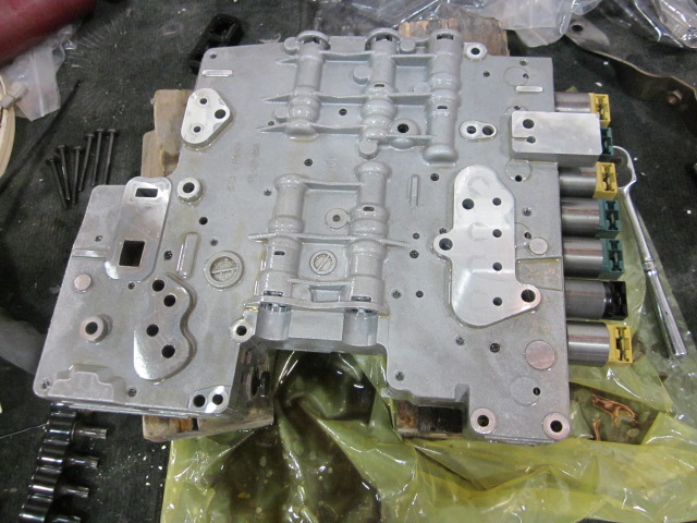
step 15: carefully lift TCM from Mechatronic. The TCM uses two metal pins that act as guides. The TCM should lift from the Mechatronic with a minimal amount of force; some gentle rocking and lifting upwards will allow it to separate. If you are unable to get it to budge, you likely have one or more bolts still holding it in place. After separating the TCM from the Mechatronic, store in a safe location. Your Mechatronic should now look like this:
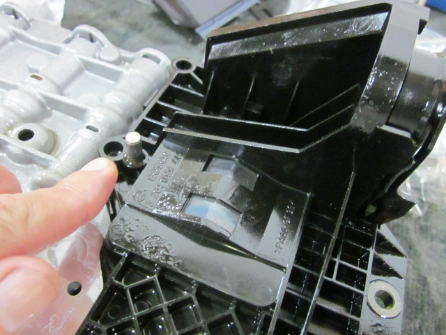
Guide pins for the TCM:
step 16: unbolt the shift solenoid retainer plate.
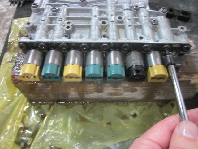
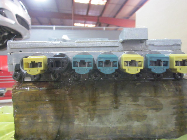
step 17: Once the retainer bolt is removed, the solenoids are ready to come out and be replaced. The solenoids can be removed by hand by pulling outward and gently twisting at the same time. I replaced mine one at a time, matching colors of the old to new as I worked my way down the line. If for some reason you see green solenoids, the replacements are blue. Match yellow to yellow, and black to black, noting the position the of solenoids before removing.
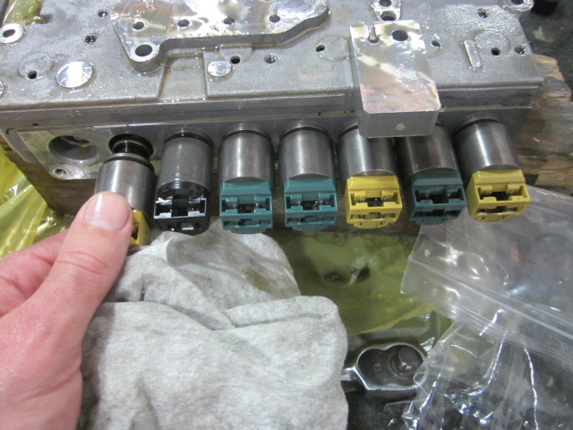
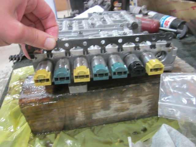
step 18: press replacement solenoids into Mechatronic by hand, ensuring that the terminals are facing in the same direction as the old solenoids that were removed. Ensure that you have the solenoids fully seated in the Mechatronic, as shown below.
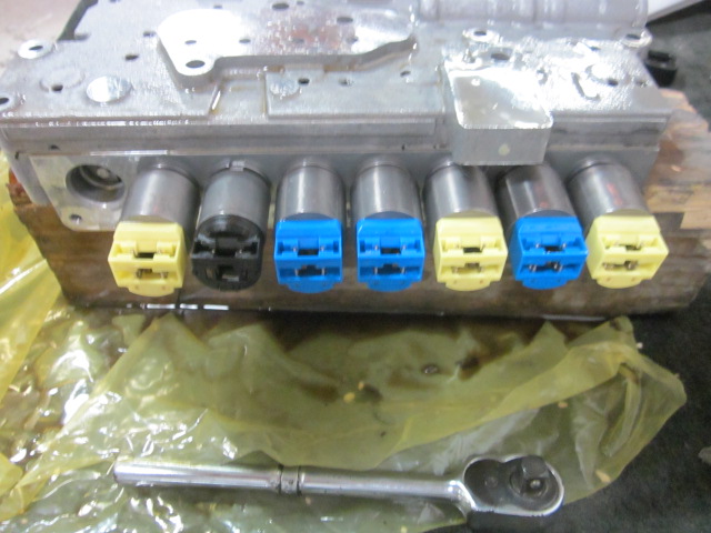
step 19: carefully lower TCM onto Mechatronic, press gently into mounting position, then remove. This will help line up all of the terminals on the solenoids to their correct mounting positions. Unless you are a robot, your solenoids will likely look like mine after you install them by hand. If the terminals are not lined up perfectly, the TCM will not fully seat against the valve body. 'Dry fitting' the TCM will aid in lining everything up.
step 20: After all of the solenoids are lined up, it's time to install the solenoid retainer plate. The retainer plate is there to fully lock the solenoids into position. Torque spec for the retainer plate bolts is 5 ft/lbs. The retainer plate can only be installed in one position; if it won't seat flat against the valve body, flip it around.
step 21: turn the TCM upside down, you should see the foam insulating strip. Remove and replace. (Sorry, forgot to take a picture of this)
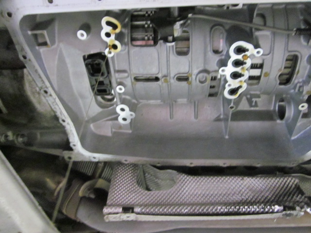
step 22: install TCM back onto Mechatronic by lining up the guide pins and gently pressing the TCM flat against the aluminum portion of the valve body. Torque spec for the TCM mounting bolts is 5 ft/lbs. You have just finished solenoid replacement, and the Mechatronic is now ready to be installed back into the transmission. Before we can install it, we need to replace the four sealing sleeves and the somewhat infamous bridge seal or 'adapter seal'
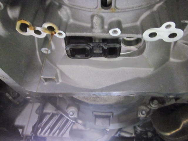
In this photo, you can clearly see the four sealing sleeves to the right, and the bridge seal to the left. These seals are a known failure point, and can cause a host of issues.
If you are simply replacing fluid, the only part you will need is replacement fluid. I would also recommend replacing the drain and fill plugs, as both contain a rubber sealing ring, as well as the oil pan gasket if your pan has never been removed.
If you are replacing the Mechatronic sealing sleeve, you will need all of the aforementioned parts along with a new sealing sleeve.
If you are performing a routine fluid and filter replacement, you will need the service kit offered by the CTSC. The transmission filter has been integrated into the pan by ZF. The pan will come with a new oil pan gasket and drain plug pre-installed.
If you are replacing shift solenoids, you will need seven liters of fluid, shift solenoid kit, the four sealing sleeves (not to be confused with the 'Mechatronic sealing sleeve'), a new Mechatronic sealing sleeve, a new bridge seal, and a new foam solenoid insulator. If your pan/filter assembly has never been changed, you should also buy a new pan, along with a new fill plug.
Before we begin, I'll mention the mandatory disclaimer: By performing any repair to your car outlined in this thread, you assume ALL RESPONSIBILITY for any damage that occurs to you, your equipment, or your car. 100% on you, 0.0% on me. I also cannot guarantee this will solve your specific problems, if there are any present. The only way to guarantee that would be to replace the entire transmission, which is exactly why BMW recommends it. However, these transmissions are repairable, and many transmission faults can be traced to failure in one or more components mentioned in this thread. Use your best judgement and carryout the repair YOU think is best for YOUR car.
This DIY also assumes you are comfortable performing somewhat complex repairs to your car, have access to all necessary tools, and are familiar with using INPA. You will need INPA to measure transmission temperature. If you don't have access to INPA, you will need to find some way to measure and monitor transmission fluid temperature.
Before we dig in I'll give you a little history on my car. I have a March of '04 build 530i, with ZF's 6HP19 automatic transmission. I bought the car with approximately 94,000 miles on it. Before I owned it, it was owned by a middle aged gentlemen who had the car serviced by BMW of Sarasota since new. So basically, my car was never 'abused' that I know of. I started experiencing some erratic shifting, along with error codes that would result in the transmission going into 'failsafe' mode. The codes I retrieved on a regular basis were 4F81 and 4F85, which reference slipping in the A clutch and E clutch of the transmission. After getting 4F85 five or six times, I knew that if I let it go too long I was going to be replacing the transmission, as slipping in the clutches will result in transmission failure. Since replacing the fluid and resetting adaptations didn't resolve the problem, I decided to dive in and replace the shift solenoids, as they are known to fail and cause the types of problems I was having. The shift solenoids are contained in the valve body, which ZF refers to as the 'Mechatronic'. I ordered all of my parts from thectsc.com. They are a great outfit to deal with, and I highly recommend them for any transmission parts needed for any of these procedures.
Before doing anything, you will need to have the car elevated on a lift or jack stands. You need to have it elevated enough to freely work completely underneath the car. If you use jack stands, please be extremely careful. Safety first, everything else is second.
Let's get started...
step 1: Remove center floor covering. The center floor covering is held my multiple fasteners of different sizes. Once all fasteners are removed, the covering will simply drop from the car without using any force.
step 2: You will need to identify your transmission by finding the serial number plate. The plate should be on the outside of the casing, near the middle, and on the left side. This serial number is important if you are replacing solenoids and related seals, as they will need to be ordered by using this serial number. Below is a picture of the plate on my car, the number that is of importance is the one that follows the text "STUECKL". My transmission's number is '1071 010005', as you can see in the photo.
step 3: Order the appropriate parts! I ordered all of mine from thectsc.com. If you need to drive the car for a few days without the floor coverings installed, be mindful of the fact that they are not there to protect your undercarriage. thectsc.com ships quickly, so you shouldn't be wating long. Once parts arrive, you are ready to proceed. Below is a picture of the parts I used for solenoid replacement, including the part number for the solenoid set that applies to my early build 6HP19.
step 4: remove transmission FILL plug. I always remove the fill plug first, because I never want to find myself in a situation where I've drained all of the fluids out of a component with no way to get new fluids back in. Yes, it has been known to happen. I highly recommend removing the fill plug first. Below is picture showing the location of the fill plug (orange tube is inserted in this picture) relative to the drain plug. The fill plug is on the left side, towards the rear. an 8mm allen wrench works best to remove it.
step 5: undo drain plug on transmission pan, drain transmission fluid into a clean drain pan. You will want to use a clean pan as the fluid should be recovered and set aside until all service is complete, as this drained fluid can be helpful if you run out of new fluid during any of these processes. While reusing old fluid is less than ideal, it is certainly better than running out completely. I used a plastic cat litter pan that held all of the drained fluid without running over. It was less that $6 and works great. Drain plug has been removed in this photo.
step 6: Allow the transmission fluid to fully drain. If you are simply replacing the transmission fluid, reinstall the drain plug and skip to step 30.
step 7: unbolt and remove the center exhaust system bracket. The bracket will need to be removed in order to fully access the transmission pan mounting screws at the rear of the pan.
step 8: Remove all transmission pan retaining screws, then lower the transmission pan from the car. Be careful when lowering the pan, as there will still be a small amount of standing fluid in the pan. You can see from this photo why we need to remove the exhaust bracket. If you are performing a routine fluid and pan/filter replacement, skip to step 29.
step 9: Unlock Mechatronic sealing sleeve by pulling down on unlocking lever. The sleeve is 'locked' into position by this lever. Unlocking the lever should NOT take much force at all. I was able to unlock it by gently pulling down with two fingers.
step 10: disconnect wiring harness connector at the Mechatronic sleeve. If you look at the connector, you will see a square tab at about the 5 o'clock position. I used a 1" wooden dowel to undo the connector. Place either a finger, dowel, or any other appropriate tool on the tab. The connector will unscrew by rotating it in a COUNTER-CLOCKWISE motion. Once the connector is fully unseated, push it up and out of the way to fully expose the Mechatronic sealing sleeve.
step 11: remove Mechatronic sealing sleeve. The mechatronic sleeve can be removed by gently rocking the sleeve from side to side while pulling it outward, either by hand or with a set of pliers. There is only a very small amount of room between the transmission and the transmission bracket, so unless you have really small hands a set of pliers similar to what I used is probably going to be the best route. These are the pliers I used, as they allowed me to get good clamping force on the sleeve while extracting it. DO NOT attempt to remove the sleeve with a twisting motion, as you risk cracking the locating tab that is molded into the Mechatronic connection point. Here you can see the sleeve relative to the locking lever, as well as the limited amount of work area you'll be dealing with. If you are only replacing the Mechatronic sealing sleeve located on the outside of the transmission, skip to step 26.
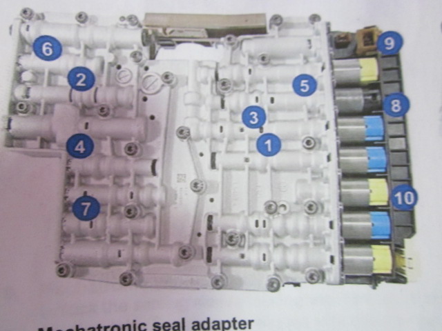
step 12: unbolt Mechatronic mounting bolts. It is very important to support the Mechatronic while you are unbolting it from the transmission. If you don't have it supported, it WILL fall on the ground, likely break, and put a $1700 dent in your wallet. It is also vital that any time you are handling the Mechatronic you do NOT allow anything to come into contact with the pins in the electrical connector. Any static electricity that is discharged into the pins will likely destroy the TCM and require replacement. Take your time and be careful!! Below are two diagrams showing the bolt pattern for the Mechatronic. Compare the stampings in yours, and remove the appropriate bolts while supporting the Mechatronic.
step 13: Carefully lower Mechatronic from transmission, and place on a clean working surface. I used a workbench with two blocks of 2x4 to support the Mechatronic while I worked with it.
step 14: remove mounting bolts securing TCM to the Mechatronic. The TCM is the computer portion of the Mechatronic, encased in black plastic. The bolts that hold the TCM to the Mechatronic are the same size as the ones that hold the two aluminum halves of the Mechatronic together. It is very important to only remove the bolts that are holding the TCM in place. By turning the mechatronic over and following the bolts from one side to the other, it should become apparent which bolts are for the TCM.
step 15: carefully lift TCM from Mechatronic. The TCM uses two metal pins that act as guides. The TCM should lift from the Mechatronic with a minimal amount of force; some gentle rocking and lifting upwards will allow it to separate. If you are unable to get it to budge, you likely have one or more bolts still holding it in place. After separating the TCM from the Mechatronic, store in a safe location. Your Mechatronic should now look like this:
Guide pins for the TCM:
step 16: unbolt the shift solenoid retainer plate.
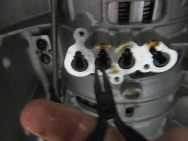
step 17: Once the retainer bolt is removed, the solenoids are ready to come out and be replaced. The solenoids can be removed by hand by pulling outward and gently twisting at the same time. I replaced mine one at a time, matching colors of the old to new as I worked my way down the line. If for some reason you see green solenoids, the replacements are blue. Match yellow to yellow, and black to black, noting the position the of solenoids before removing.
step 18: press replacement solenoids into Mechatronic by hand, ensuring that the terminals are facing in the same direction as the old solenoids that were removed. Ensure that you have the solenoids fully seated in the Mechatronic, as shown below.
step 19: carefully lower TCM onto Mechatronic, press gently into mounting position, then remove. This will help line up all of the terminals on the solenoids to their correct mounting positions. Unless you are a robot, your solenoids will likely look like mine after you install them by hand. If the terminals are not lined up perfectly, the TCM will not fully seat against the valve body. 'Dry fitting' the TCM will aid in lining everything up.
step 20: After all of the solenoids are lined up, it's time to install the solenoid retainer plate. The retainer plate is there to fully lock the solenoids into position. Torque spec for the retainer plate bolts is 5 ft/lbs. The retainer plate can only be installed in one position; if it won't seat flat against the valve body, flip it around.
step 21: turn the TCM upside down, you should see the foam insulating strip. Remove and replace. (Sorry, forgot to take a picture of this)
step 22: install TCM back onto Mechatronic by lining up the guide pins and gently pressing the TCM flat against the aluminum portion of the valve body. Torque spec for the TCM mounting bolts is 5 ft/lbs. You have just finished solenoid replacement, and the Mechatronic is now ready to be installed back into the transmission. Before we can install it, we need to replace the four sealing sleeves and the somewhat infamous bridge seal or 'adapter seal'
In this photo, you can clearly see the four sealing sleeves to the right, and the bridge seal to the left. These seals are a known failure point, and can cause a host of issues.
Last edited by KyleB; 03-28-2014 at 04:55 PM.
03-27-2014, 05:13 PM
#7
Members
Senior Members
Join Date: May 2012
Location: Tampa Bay, FL
Posts: 2,539
Likes: 0
Received 10 Likes
on
6 Posts
My Ride: 530i
Model Year: 2004
Engine: M54
step 23: Remove the bridge seal from transmission by simply pulling it away from the transmission.
step 24: The next step is replacing the four sealing sleeves. In my 6HP19, only two of the sleeves were of the same size. You should have one long, one medium, and two short sleeves in your replacement set. using a small set of needle nosed pliers, remove and replace each sleeve one by one, noting the position of each sleeve as they are replaced. A moderate amount of force may be required to remove them, and they can be pressed into place by hand. Apologies for the blurry photo, but you get the idea.
step 25: Carefully lift Mechatronic into position. While supporting the Mechatronic, install all mounting bolts and hand tighten to hold the Mechatronic in place. Torque all Mechatronic mouting bolts in the sequence outlined below, depending on which diagram pertains to your car. Torque spec is 8nm.

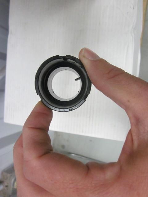
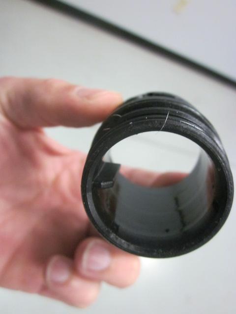
step 26: Install Mechatronic sealing sleeve. Before attempting to install the new sleeve, lightly coat the two o-rings in the middle with Vaseline. The Mechatronic has a locating tab that is molded into the connection socket. The locating tab is at around the 5 o'clock position, so you will need to match the slot in the sleeve with the locating tab on the Mechatronic. the best way to do this is to align the sleeve with the socket, and slowly rotate it while putting a small amount of inward pressure on the sleeve. When you get it right, you'll feel the tab catch the slot on the sleeve. Then it is a matter of putting inward pressure on the sleeve to get it to fully press into place. If you don't have small hands, go rent a skinny guy. Seriously, there is hardly any room between the transmission support and transmission tunnel. You'll be able to get only one hand in there, so take your time. These two photos show the locating tab that is molded into the sleeve, the tab engages in the slot on the actual Mechatronic.
step 27: lock Mechatronic sealing sleeve into place by pushing up on locking lever. The locking lever should be able to move into its correct 'locked' position with minimal force. If the lever will not move, check to see that the sealing sleeve is pressed into place enough, and is not crooked. This photo shows how the sleeve should be positioned if installed correctly.

step 28: Resecure the wiring harness connector to Mechatronic. By now, you probably noticed that the sealing sleeve is threaded. Plug the connector onto the Mechatronic, and once partially seated rotate the tab on the connector clockwise until you feel it 'bump' into the locked position. If you have it right, the connector will sit flush with the sleeve, and the connector will rotate and lock into place with a minimal amount of force. This can be done by hand, and once again you will be dealing with very small amount of space to work with.
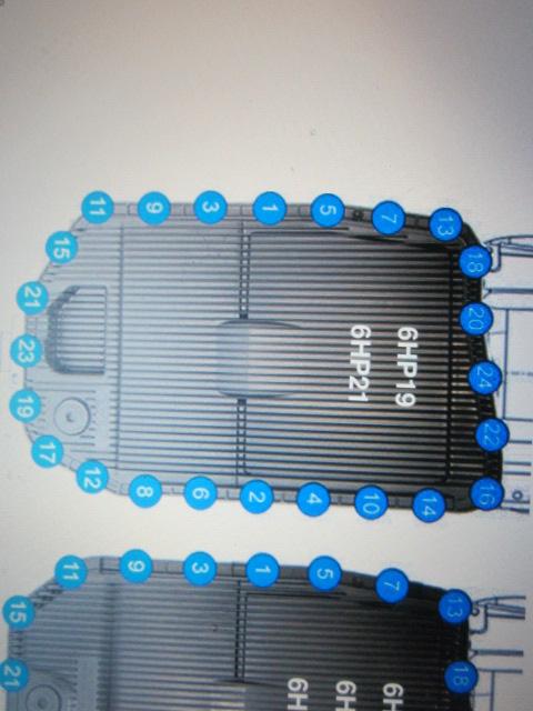
step 29: install transmission pan with drain plug reinstalled, using the tightening sequence shown below. The picture below is the tightening squence for the 6HP19; 6HP26 may be different. If you are using a new transmission pan, the drain plug should already have been preinstalled by ZF. Torque spec for the pan screws is 10nm, or around 7.5 ft/lbs. I highly recommend replacing all of your pan screws with new ones from ZF if this is the first time you are replacing your transmission pan.
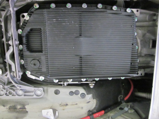
step 30: We're now ready to refill the transmission. You will need some sort of pumping device to extract fluid from the bottle and pump it into the transmission. I used a fluid pump I got from Harbor Freight, and it did the job very well. It was around $7, and could empty a 1L bottle of Lifeguard6 in about 6 pumps. Place one line into the transmission filling orifice, and the other into the transmission fluid container. With the engine OFF, continue to pump new transmission fluid into the transmission until you see it begin to stream out of the filling orifice. Once you see fluid coming back out of the orifice as you pump, install the fill plug HAND TIGHT.
step 31: Start the engine, and allow to idle for approximately 15 to 30 seconds. Undo the fill plug, exposing the filling orifice. NO fluid should come out of the filling orifice. position your fluid pump with the suction line in a fluid container, and the other end inside of the filling orifice
step 32: For those with INPA, connect your laptop to the car and load INPA. For those without INPA, this is the point where you will need to start monitoring transmission temperature. Use a suitable tool to do so.
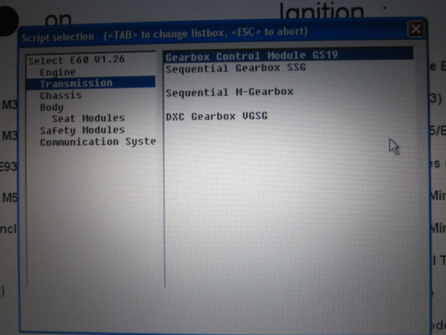
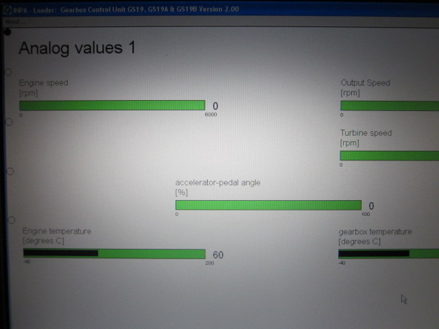
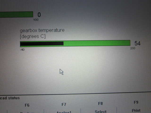
step 33: Access transmission temperature monitoring screen. With INPA loaded, press F6 for 'E60', select GS19 transmission control, F5 for status, then F7 for 'analog values'. This will allow you to monitor transmission temperature. This is what you should be seeing, and how you got there:
step 34: After transmission temperature has reached 40C, continue to fill transmission. While filling transmission, place selector into Steptronic mode and shift through programs M1 through M3, holding each gear for approximately five seconds. Place transmission back into park while fluid continues to be pumped into transmission. Pump as quickly as possible, as the transmission will go from 40C to 50C a lot faster than you would think.
step 35: CLOSELY MONITOR TRANSMISSION TEMPERATURE DURING THE FILLING PROCESS. If transmission temperature reaches 50C, install the fill plug hand tight, turn the car off, and allow the transmission temperature to cool back down to approximately 40C before restarting the final fill process.
step 36: Once transmission fluid begins to emerge from the filling orifice with the engine still running, install the fill plug. Torque spec is 35nm. Space is limited, and I was not able to get a torque wrench on the fill plug. I simply tightened it by hand fairly snug as I would any other metal drain plug.
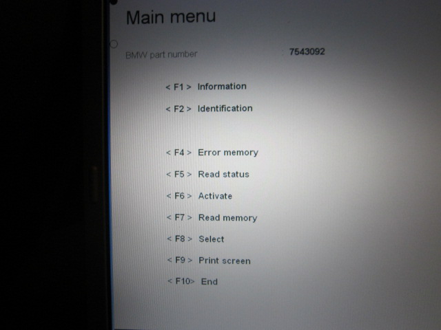
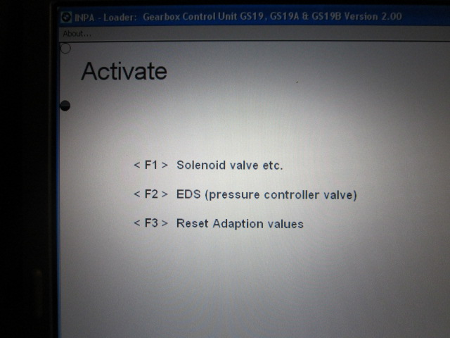
step 37: reset adaptations using INPA. To do this, start again at the main INPA screen. Select F6 for 'E60', then select and double click on 'Gearbox Control GS19'. press F6 for 'Activate', then F3 to reset adaptations. Adaptations have now been reset!
step 38: reinstall floor coverings
You are now ready to test drive the car. DO NOT PANIC if your car now shifts very poorly, with somewhat harsh upshifts and downshifts. By all accounts, this is normal due to the fact that adaptations have been reset. The TCM needs to 'relearn' not only your driving habits, but also the amount of normal wear that is present in the clutch packs inside of the transmission. Most, if not all of this 'learning' process should be complete after approximately 100 miles of driving. I also highly recommend reinspecting the transmission for external leaks at some point after 100 miles of driving.
One final note; if you order your parts from the CTSC, the owner will gladly send you a PDF document with instructions. I recommend using those, along with this thread, to help you with the process. You may notice some slight differences between this thread and the instructions the CTSC provides. Use your judgement and do what works best for you.
Best of luck to everyone. If you think I can offer any further advice feel free to PM me and I will respond when I can.
step 24: The next step is replacing the four sealing sleeves. In my 6HP19, only two of the sleeves were of the same size. You should have one long, one medium, and two short sleeves in your replacement set. using a small set of needle nosed pliers, remove and replace each sleeve one by one, noting the position of each sleeve as they are replaced. A moderate amount of force may be required to remove them, and they can be pressed into place by hand. Apologies for the blurry photo, but you get the idea.
step 25: Carefully lift Mechatronic into position. While supporting the Mechatronic, install all mounting bolts and hand tighten to hold the Mechatronic in place. Torque all Mechatronic mouting bolts in the sequence outlined below, depending on which diagram pertains to your car. Torque spec is 8nm.
step 26: Install Mechatronic sealing sleeve. Before attempting to install the new sleeve, lightly coat the two o-rings in the middle with Vaseline. The Mechatronic has a locating tab that is molded into the connection socket. The locating tab is at around the 5 o'clock position, so you will need to match the slot in the sleeve with the locating tab on the Mechatronic. the best way to do this is to align the sleeve with the socket, and slowly rotate it while putting a small amount of inward pressure on the sleeve. When you get it right, you'll feel the tab catch the slot on the sleeve. Then it is a matter of putting inward pressure on the sleeve to get it to fully press into place. If you don't have small hands, go rent a skinny guy. Seriously, there is hardly any room between the transmission support and transmission tunnel. You'll be able to get only one hand in there, so take your time. These two photos show the locating tab that is molded into the sleeve, the tab engages in the slot on the actual Mechatronic.
step 27: lock Mechatronic sealing sleeve into place by pushing up on locking lever. The locking lever should be able to move into its correct 'locked' position with minimal force. If the lever will not move, check to see that the sealing sleeve is pressed into place enough, and is not crooked. This photo shows how the sleeve should be positioned if installed correctly.
step 28: Resecure the wiring harness connector to Mechatronic. By now, you probably noticed that the sealing sleeve is threaded. Plug the connector onto the Mechatronic, and once partially seated rotate the tab on the connector clockwise until you feel it 'bump' into the locked position. If you have it right, the connector will sit flush with the sleeve, and the connector will rotate and lock into place with a minimal amount of force. This can be done by hand, and once again you will be dealing with very small amount of space to work with.
step 29: install transmission pan with drain plug reinstalled, using the tightening sequence shown below. The picture below is the tightening squence for the 6HP19; 6HP26 may be different. If you are using a new transmission pan, the drain plug should already have been preinstalled by ZF. Torque spec for the pan screws is 10nm, or around 7.5 ft/lbs. I highly recommend replacing all of your pan screws with new ones from ZF if this is the first time you are replacing your transmission pan.
step 30: We're now ready to refill the transmission. You will need some sort of pumping device to extract fluid from the bottle and pump it into the transmission. I used a fluid pump I got from Harbor Freight, and it did the job very well. It was around $7, and could empty a 1L bottle of Lifeguard6 in about 6 pumps. Place one line into the transmission filling orifice, and the other into the transmission fluid container. With the engine OFF, continue to pump new transmission fluid into the transmission until you see it begin to stream out of the filling orifice. Once you see fluid coming back out of the orifice as you pump, install the fill plug HAND TIGHT.
step 31: Start the engine, and allow to idle for approximately 15 to 30 seconds. Undo the fill plug, exposing the filling orifice. NO fluid should come out of the filling orifice. position your fluid pump with the suction line in a fluid container, and the other end inside of the filling orifice
step 32: For those with INPA, connect your laptop to the car and load INPA. For those without INPA, this is the point where you will need to start monitoring transmission temperature. Use a suitable tool to do so.
step 33: Access transmission temperature monitoring screen. With INPA loaded, press F6 for 'E60', select GS19 transmission control, F5 for status, then F7 for 'analog values'. This will allow you to monitor transmission temperature. This is what you should be seeing, and how you got there:
step 34: After transmission temperature has reached 40C, continue to fill transmission. While filling transmission, place selector into Steptronic mode and shift through programs M1 through M3, holding each gear for approximately five seconds. Place transmission back into park while fluid continues to be pumped into transmission. Pump as quickly as possible, as the transmission will go from 40C to 50C a lot faster than you would think.
step 35: CLOSELY MONITOR TRANSMISSION TEMPERATURE DURING THE FILLING PROCESS. If transmission temperature reaches 50C, install the fill plug hand tight, turn the car off, and allow the transmission temperature to cool back down to approximately 40C before restarting the final fill process.
step 36: Once transmission fluid begins to emerge from the filling orifice with the engine still running, install the fill plug. Torque spec is 35nm. Space is limited, and I was not able to get a torque wrench on the fill plug. I simply tightened it by hand fairly snug as I would any other metal drain plug.
step 37: reset adaptations using INPA. To do this, start again at the main INPA screen. Select F6 for 'E60', then select and double click on 'Gearbox Control GS19'. press F6 for 'Activate', then F3 to reset adaptations. Adaptations have now been reset!
step 38: reinstall floor coverings
You are now ready to test drive the car. DO NOT PANIC if your car now shifts very poorly, with somewhat harsh upshifts and downshifts. By all accounts, this is normal due to the fact that adaptations have been reset. The TCM needs to 'relearn' not only your driving habits, but also the amount of normal wear that is present in the clutch packs inside of the transmission. Most, if not all of this 'learning' process should be complete after approximately 100 miles of driving. I also highly recommend reinspecting the transmission for external leaks at some point after 100 miles of driving.
One final note; if you order your parts from the CTSC, the owner will gladly send you a PDF document with instructions. I recommend using those, along with this thread, to help you with the process. You may notice some slight differences between this thread and the instructions the CTSC provides. Use your judgement and do what works best for you.
Best of luck to everyone. If you think I can offer any further advice feel free to PM me and I will respond when I can.
Last edited by KyleB; 03-28-2014 at 04:54 PM.


