How To: Fit a 7" VRSF Intercooler to your E6X N54 chassis
 05-03-2014, 09:56 AM
#1
Members
Senior Members
Thread Starter
Gentlemen,
As we all know, the E6X chassis does not get much love in the N54 tuning world. I hope my contributions can help expand the options for those who are in the market for an aftermarket intercooler (IC). After much researching I pulled the trigger on a 7" VRSF IC; it's not a direct bolt-on for the 5 series but I was confident it could be fitted with some creativity.
There were some additional parts I needed to complete the install. I ordered the optional 9" 90 degree pipe with my IC but did not utilize it.
ADDITIONAL PIPING
- 15" 90 degree aluminum elbow 2.5"
- 5" aluminum joiner 2.5"
- 45 degree silicone elbow 2.5"
- 30 degree silicone elbow 2.5"
- 4 T-Bolt Clamps 2.5"
I sourced the parts from Max-Redline and Silicone Intakes.
Here is what I did to make it fit on my car. Just like riding downhill mountain bikes, "follow me at your own risk." :character0264:
-Evan
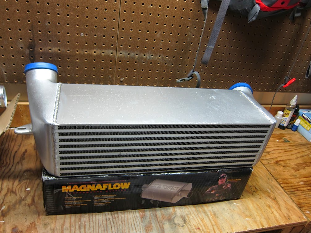
1. Unboxed the IC and all looked good, it was well packed and the IC passed my initial quality inspection. If I had to get picky: my IC was painted silver and the paint was still damp in some places, I would prefer to have a raw/polished piece but that is my personal preference.
2. Close up: it looks as the rows of fins are offset for better exposure.

3. Inside the end tank.

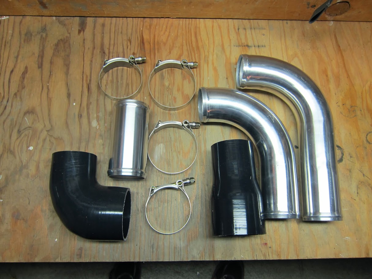
4. I optioned to get the 9" Lower Charge Pipe (LCP) from VRSF in case I had a use for it (ended up not). In addition to the included VRSF hardware this picture shows the 5" joiner and 15" 90 degree pipe I used.
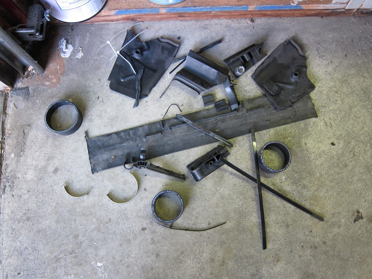
5. This piece must be removed, I originally cut it here.

6. I did the same thing on the driver side.

7. On second thought I needed to make additional room on the passenger for my Transmission Oil Cooler (TOC). This entire trim piece can be removed with one screw and this rubber/plastic piece is soft enough to be cut with a sharp utility knife. You can see the different in the cleanliness of the cuts below (dremel vs razor).

8. Relocating the TOC is one of the hurdles with the E6X platform. When initially inspecting my car to see if the IC install would even be possible; I was happy find that the TOC had some soft lines in addition to the hard. There was also enough length on soft lines to allow some movement of the core.
This is how I relocated the TOC, simple and effective in my opinion. It does cover the lower 1/3 of the power steering cooler but I am not terribly worried about that. It also sits in front of the radiator but it is such a small % of the radiator's core, I am again not worried; especially when people are running huge V-mount ICs with no notable decrease in radiator performance.
Also, I bet the TOC is able to perform much better in this location with the direct air flow compared to the oem air scoop design which not only collected tons of road debris but also blocked airflow to the oem IC. I mounted it with a couple zip ties as "less is more" when working with things that require maximum air flow.

9. Another view.

10. Showing the stress-free hose routing for the TOC, this could not have worked out much better.

11. This was taken after I trimmed the L shaped piece of hard plastic trim that usually covers the oem end tanks.

12. There is a piece plastic which separated the radiator and oem IC. I would say removing this piece is optional but I chose to do it as it is advantageous to mount the IC as high as possible to maximize direct air flow.

13. The radiator-fan shroud must be trimmed at the lower corners to fit the VRSF end tanks. I took about 1" off. Do this to both sides.
Please note that depending on your IC piping, you may want to trim the bottom edge of the radiator-fan shroud, I did this thinking my IC would be mounted completely level. As it turns out my IC sits with the front tilted upward slightly; it helps maximize the surface area exposed to direct airflow but I now have a small gap between the back of my IC and the lower radiator-fan shroud, it is not a big deal but if that lower shroud was still in place it would help pull more air through the IC. It all depends on your setup so I recommend finalizing your mounting position and trim or not trim the shroud accordingly.

14. Comparison Shot 1

15. Comparison Shot 2

16. Comparison Shot 3
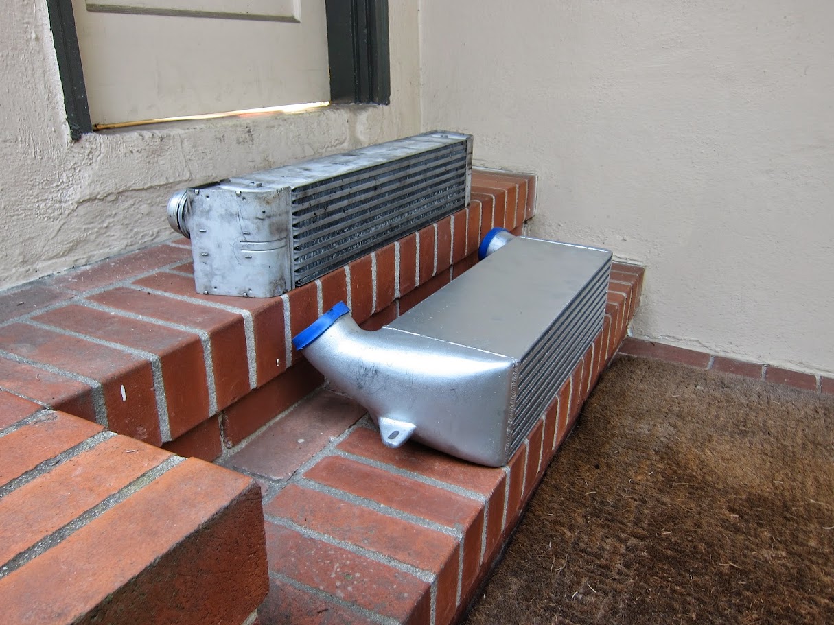
17. Comparison Shot 4

18. This is how the VRSF IC fits. The original E9X tabs and just below the bracket that holds the oem IC bottom tray.

19. I decided to replace the elbow that connects the LCP and oem Charge Pipe (CP). The clamp connecting the elbow and CP does not have a screw or bolt and much be cut off, it took me a while with a dremel. If you are careful not to cut through the elbow itself it can be remounted with a basic T-bolt clamp.

20. Here is the replaced 30 degree silicone elbow. This may change depending on fitment with my VRSF CP but it works for now with the oem CP. You can also see the upper clearance on the LCP. Make sure those T-bolts are tight!

21. Clearance of the LCP.

22. The supplied silicone reducer was nowhere near making it to the metal piping from the turbos (remember this kit if made for a E9X). An additional 45 degree elbow and 5" aluminum joiner make ends meet. I trimmed both ends of the 45 a bit and the end tank side of the reducer to fine tune the fitment.

23. The IC mounting ears are just slightly narrower than the stock IC brackets. If they were about 1" wider then mounting the IC with nuts and bolts would have been an easy and reliable mounting solution. It is possible to use some screws but the angle would be awkward and it would look hideous ...keep it clean!
I originally wanted to make some bracket templates that could be taken to a machine shop, machined, and later welded. Although I still might go this route, it turned out to be more work and money than expected, especially considering the effectiveness of my temporary-yet-long term mounting solution.
I decided to run some big-manly zipties and drilled some holes through the bottom 3 layers and the inner wall of the bracket to alleviate unnecessary stress on the ties and also help clean up the aesthetics. This was intended to be a temporary solution and I even bought some plumbers tape and washers to support the bottom of the IC but did not need it. I even drove the car around without the bumper on to check for boost leaks (none) and I wasn't concerned about the security of the IC; it is extremely solid, just make sure you have jumbo legit zip-ties ...legit ties!

24. Zip tie routing. I feel having the male and female intersection of the tie angled at 90 degrees not only helps aesthetics but maximizes strength.

25. Ready for final installation

26. IC mounted. Please notice the bumper/TOC/IC relation, it is about as good as it can get and I am pleased with the way it turned out.

27. Zip ties under load and they seem content.

28. The parts that didn't make it.
29. Fitted #1
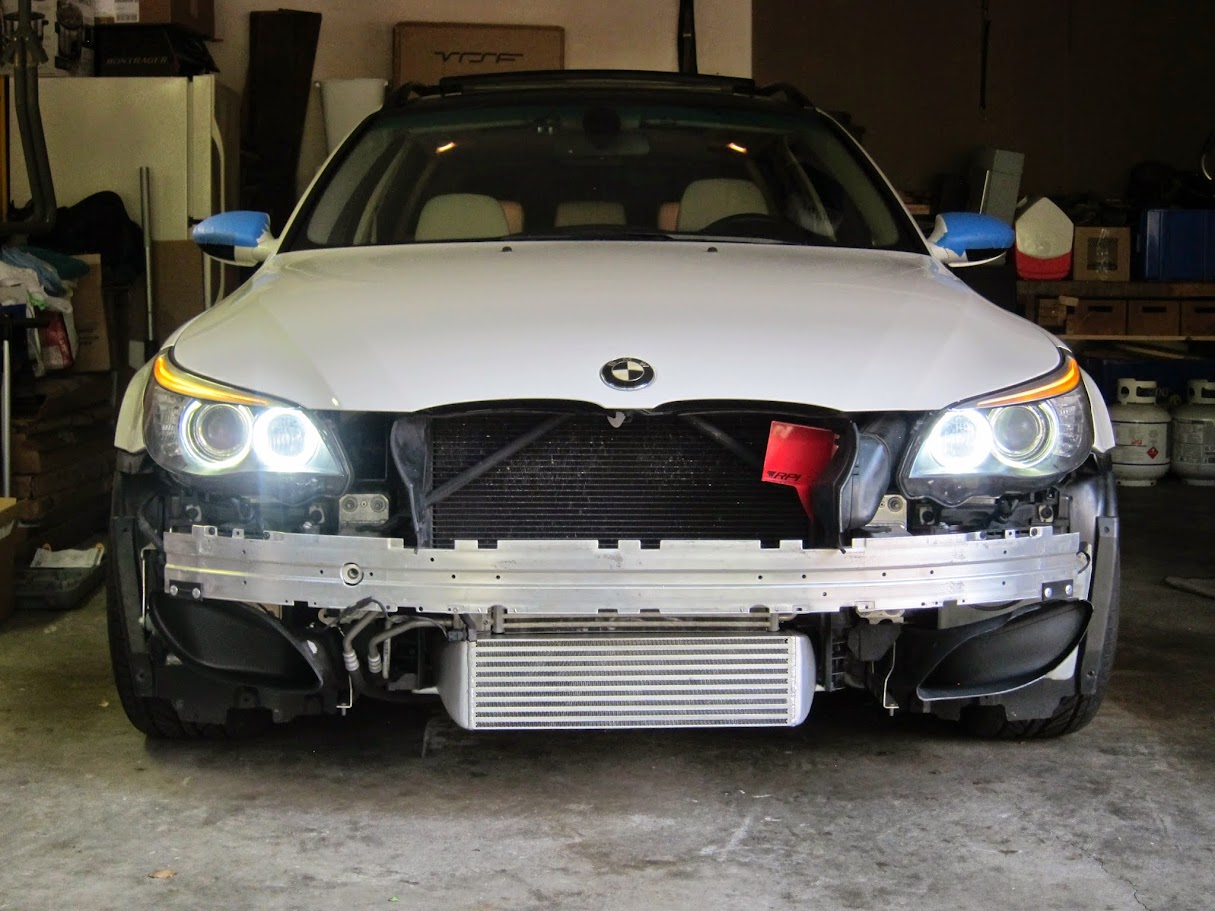
30. Fitted #2

31. Fitted #3

32. Fitted #4

33. Fits in there well considering it's size.

34. Don't mind the tape, I got my front bumper and mirrors resprayed at LTMW and wanted it protected for my drive up to the Bay Area. Besides IC install > painters tape.
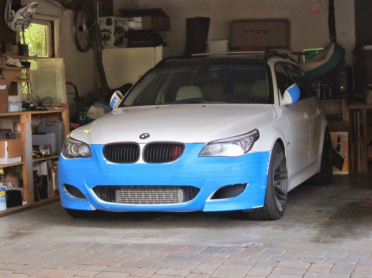
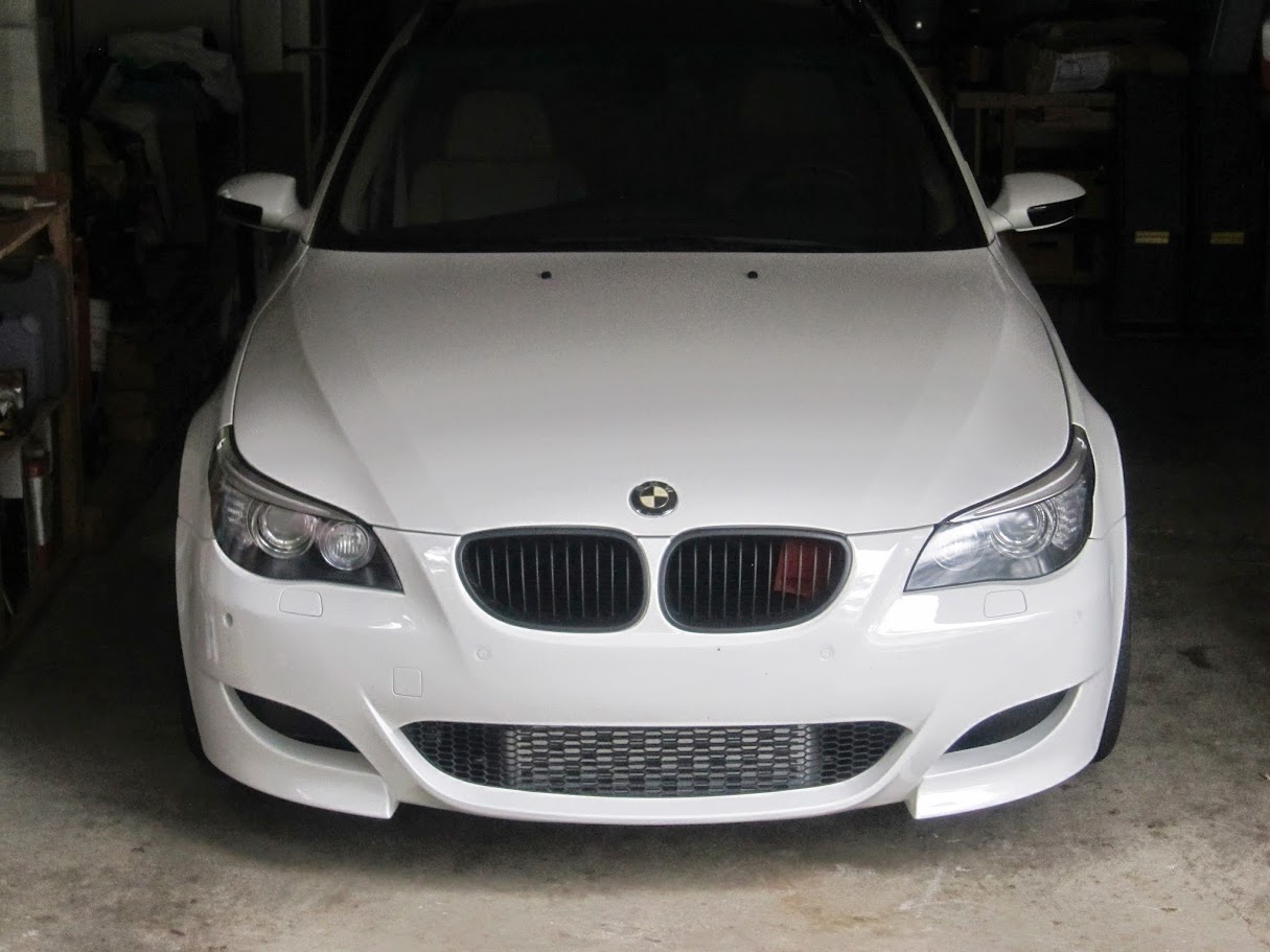
35. Fitted #5

35. Fitted #6
As we all know, the E6X chassis does not get much love in the N54 tuning world. I hope my contributions can help expand the options for those who are in the market for an aftermarket intercooler (IC). After much researching I pulled the trigger on a 7" VRSF IC; it's not a direct bolt-on for the 5 series but I was confident it could be fitted with some creativity.
There were some additional parts I needed to complete the install. I ordered the optional 9" 90 degree pipe with my IC but did not utilize it.
ADDITIONAL PIPING
- 15" 90 degree aluminum elbow 2.5"
- 5" aluminum joiner 2.5"
- 45 degree silicone elbow 2.5"
- 30 degree silicone elbow 2.5"
- 4 T-Bolt Clamps 2.5"
I sourced the parts from Max-Redline and Silicone Intakes.
Here is what I did to make it fit on my car. Just like riding downhill mountain bikes, "follow me at your own risk." :character0264:
-Evan
1. Unboxed the IC and all looked good, it was well packed and the IC passed my initial quality inspection. If I had to get picky: my IC was painted silver and the paint was still damp in some places, I would prefer to have a raw/polished piece but that is my personal preference.
2. Close up: it looks as the rows of fins are offset for better exposure.
3. Inside the end tank.
4. I optioned to get the 9" Lower Charge Pipe (LCP) from VRSF in case I had a use for it (ended up not). In addition to the included VRSF hardware this picture shows the 5" joiner and 15" 90 degree pipe I used.
5. This piece must be removed, I originally cut it here.
6. I did the same thing on the driver side.
7. On second thought I needed to make additional room on the passenger for my Transmission Oil Cooler (TOC). This entire trim piece can be removed with one screw and this rubber/plastic piece is soft enough to be cut with a sharp utility knife. You can see the different in the cleanliness of the cuts below (dremel vs razor).
8. Relocating the TOC is one of the hurdles with the E6X platform. When initially inspecting my car to see if the IC install would even be possible; I was happy find that the TOC had some soft lines in addition to the hard. There was also enough length on soft lines to allow some movement of the core.
This is how I relocated the TOC, simple and effective in my opinion. It does cover the lower 1/3 of the power steering cooler but I am not terribly worried about that. It also sits in front of the radiator but it is such a small % of the radiator's core, I am again not worried; especially when people are running huge V-mount ICs with no notable decrease in radiator performance.
Also, I bet the TOC is able to perform much better in this location with the direct air flow compared to the oem air scoop design which not only collected tons of road debris but also blocked airflow to the oem IC. I mounted it with a couple zip ties as "less is more" when working with things that require maximum air flow.
9. Another view.
10. Showing the stress-free hose routing for the TOC, this could not have worked out much better.
11. This was taken after I trimmed the L shaped piece of hard plastic trim that usually covers the oem end tanks.
12. There is a piece plastic which separated the radiator and oem IC. I would say removing this piece is optional but I chose to do it as it is advantageous to mount the IC as high as possible to maximize direct air flow.
13. The radiator-fan shroud must be trimmed at the lower corners to fit the VRSF end tanks. I took about 1" off. Do this to both sides.
Please note that depending on your IC piping, you may want to trim the bottom edge of the radiator-fan shroud, I did this thinking my IC would be mounted completely level. As it turns out my IC sits with the front tilted upward slightly; it helps maximize the surface area exposed to direct airflow but I now have a small gap between the back of my IC and the lower radiator-fan shroud, it is not a big deal but if that lower shroud was still in place it would help pull more air through the IC. It all depends on your setup so I recommend finalizing your mounting position and trim or not trim the shroud accordingly.
14. Comparison Shot 1
15. Comparison Shot 2
16. Comparison Shot 3
17. Comparison Shot 4
18. This is how the VRSF IC fits. The original E9X tabs and just below the bracket that holds the oem IC bottom tray.
19. I decided to replace the elbow that connects the LCP and oem Charge Pipe (CP). The clamp connecting the elbow and CP does not have a screw or bolt and much be cut off, it took me a while with a dremel. If you are careful not to cut through the elbow itself it can be remounted with a basic T-bolt clamp.
20. Here is the replaced 30 degree silicone elbow. This may change depending on fitment with my VRSF CP but it works for now with the oem CP. You can also see the upper clearance on the LCP. Make sure those T-bolts are tight!
21. Clearance of the LCP.
22. The supplied silicone reducer was nowhere near making it to the metal piping from the turbos (remember this kit if made for a E9X). An additional 45 degree elbow and 5" aluminum joiner make ends meet. I trimmed both ends of the 45 a bit and the end tank side of the reducer to fine tune the fitment.
23. The IC mounting ears are just slightly narrower than the stock IC brackets. If they were about 1" wider then mounting the IC with nuts and bolts would have been an easy and reliable mounting solution. It is possible to use some screws but the angle would be awkward and it would look hideous ...keep it clean!
I originally wanted to make some bracket templates that could be taken to a machine shop, machined, and later welded. Although I still might go this route, it turned out to be more work and money than expected, especially considering the effectiveness of my temporary-yet-long term mounting solution.
I decided to run some big-manly zipties and drilled some holes through the bottom 3 layers and the inner wall of the bracket to alleviate unnecessary stress on the ties and also help clean up the aesthetics. This was intended to be a temporary solution and I even bought some plumbers tape and washers to support the bottom of the IC but did not need it. I even drove the car around without the bumper on to check for boost leaks (none) and I wasn't concerned about the security of the IC; it is extremely solid, just make sure you have jumbo legit zip-ties ...legit ties!
24. Zip tie routing. I feel having the male and female intersection of the tie angled at 90 degrees not only helps aesthetics but maximizes strength.
25. Ready for final installation
26. IC mounted. Please notice the bumper/TOC/IC relation, it is about as good as it can get and I am pleased with the way it turned out.
27. Zip ties under load and they seem content.
28. The parts that didn't make it.
29. Fitted #1
30. Fitted #2
31. Fitted #3
32. Fitted #4
33. Fits in there well considering it's size.
34. Don't mind the tape, I got my front bumper and mirrors resprayed at LTMW and wanted it protected for my drive up to the Bay Area. Besides IC install > painters tape.
35. Fitted #5
35. Fitted #6
 05-03-2014, 01:56 PM
#2

What can we say, NICE, GREAT job
This is the last mod to make my my car FBO
Congrats
P.S.
Tell us more on how it runs and feels ( with what mods ) before and after
NICE !!
This is the last mod to make my my car FBO
Congrats
P.S.
Tell us more on how it runs and feels ( with what mods ) before and after
NICE !!
The following users liked this post:
Skrillah416 (12-21-2019)
05-03-2014, 04:37 PM
#3
New Members

Join Date: Jul 2012
Location: NYC
Posts: 49
Likes: 0
Received 0 Likes
on
0 Posts
My Ride: 2009 535i xdrive --- JB4 G5 iso --- BMS intake --- e85 ---
Model Year: 2009
05-04-2014, 05:50 AM
#4
Senior Members
Join Date: Jan 2011
Location: UpState SC
Posts: 2,348
Likes: 0
Received 3 Likes
on
3 Posts
My Ride: 2008 535i LCI with sports/premium package, Sports trans with paddle shifters, CF emblems, JB4 Software, Dinan Exhaust, Navigation, M5Tech body kit, Carbon wrap interrior trim and CIC Controller.
Same here, GREAT WRITE-UP! Have you noticed any difference in the car? What are the cost factors in all of this as a DIY? The different finning is exactly like you said. They are designed to create different effects of airflow. Some are smooth and others have dimples to intentionally turbulate the airflow. This cooler looks quite a bit larger so I would imagine there would be a pretty good difference in the cooled exiting.
Last edited by tonyb635; 05-04-2014 at 05:54 AM.
05-04-2014, 09:18 AM
#5
Members
Senior Members
Thread Starter
Thanks for the kind words, I am happy to give back to the community.
The additional parts I sourced came to about $85. It took me probably 7 hours or so to complete the install but that was due to me such a slow and methodical worker. If I had to do it all over again it would be done in 2-3 hours; someone following my instructions should be able to get it done in 3-4 hours. I enjoy working on my car so it is time well spent.
Noticeable gains are increased top end power and IATs are staying much lower while under boost. Previously the car felt like it ran out of steam on the top end; the torque-hp ratio feels more balanced and the car rips harder towards redline.
I crunched some number on my old data logs along with my post-IC install. I focused on the IAT variation during the pulls rather than the outright numbers as it would be even less fair. Most Pre-IC logs were during warmer evenings last summer and the 3 post-IC logs were taken on a 60 degree morning.
Pre-IC logs the car was runing JB4 Map 5, BMS DCI, Muffler Delete 91oct but some pulls had a tank of around 98oct.
Boost was around 12-13psi and the IATS climbed an average of 40 degrees.
Post-IC the car had the secondary cats deleted (replaced with straight through resonators) and also about 28% of E85 in a 91oct tank.
Boost was around 16-17psi and the IATS climbed an average on 14 degrees.
Again, not a level playing ground for the comparison but it is apparent the IC is working and working well. I am eager to see how it performs during the summer when temps rise. ..........aaaaand when I get my charge pipe, AR downpipes, and custom exhaust installed.
Evan

 05-05-2014, 01:02 AM
#8
Members
Senior Members
Join Date: Apr 2012
Location: Concord, CA
Posts: 953
Likes: 0
Received 0 Likes
on
0 Posts
My Ride: Alpine E60, '09 535i-Premium, Sport and Comfort Access PackageMods: Lux H8 V3 Angel Eyes, Weisslicht LED license plate lights, Interior LED lights, RPI Scoop, Matte Black Grills, Smoked LED side markers & side reflectors, 35% tint all around, and a 3
Looks good.
05-13-2014, 08:22 AM
#9
New Members

Join Date: Oct 2012
Posts: 44
Likes: 0
Received 0 Likes
on
0 Posts
I'm going for this project as this IC seems better built as well as a good deal less expensive than any E60 dedicated applications out there. I'm having trouble sourcing the 5"coupler as Max-Redline only has an 8" listed. Any hints? Also, did you get around to selecting a CP? I'm going with meth as well and would like to do the install all in one shot but I'm not sure which CP to get. It looks like any differences can be made up by trimming the silicone couplers as you have done but, what are your thoughts?
05-14-2014, 07:07 AM
#10
Members
Senior Members
Thread Starter
I'm going for this project as this IC seems better built as well as a good deal less expensive than any E60 dedicated applications out there. I'm having trouble sourcing the 5"coupler as Max-Redline only has an 8" listed. Any hints? Also, did you get around to selecting a CP? I'm going with meth as well and would like to do the install all in one shot but I'm not sure which CP to get. It looks like any differences can be made up by trimming the silicone couplers as you have done but, what are your thoughts?
I originally ordered a VRSF CP along with my IC to see if it would fit. Tiago had never tried fitting it to an E6X and after inspecting pictures of the unit online the BOV flange location look favorable and the overall design seemed similar to CPE CP(which fit universally on all n54 platforms). Unfortunately it did not fit and I ended up ordering an ER Racewerks CP. Due to the fact the demand for them is low, they are made to order and I am still waiting to recieve it. I will report back after it is all installed. The good thing about ordering parts from SiliconeIntakes.com is they have a great return policy; I ordered a few additional sizes/bends of elbows to perfect the routing of the pipes. The pieces I don't use will be returned and refunded.
Hope this helps,
Evan