DIY Retrofit extended lights package ambient led lights to doors
 05-05-2009, 12:06 PM
#1
Contributors
Thread Starter

Join Date: Nov 2005
Location: London, UK
Posts: 4,719
Likes: 0
Received 3 Likes
on
3 Posts
My Ride: BMW E60 520d SE Saloon M47 2.0dTitanium Grey II, Grey−Dakota Leather, Visibility Package, Media Package, Through Load System, Lumbar support − fr seats, Automatic Air Conditioning−Advanced, High beam assistant, Hi−Fi Loudspeak
Model Year: 2006
Please read this thread in conjunction with this one http://forums.e60.net/index.php?showtopic=61259&hl= because he did it first. I just made it plug and play.
I'll just cover the bits that are missing from that DIY.
There are basically atleast two configuration for the doors.
1. Models with Door Modules.
2. Models without Door Modules.
Both the DIY linked and my car are the later versions without the door modules.
Don't bother putting any resistors in series with the LEDs because the signal is already current limited and adding resistors will just make the LEDs are lot dimmer.
Definately spend money and buy the OEM LEDs because they come in a housing that clicks into the openings and at the correct angle. The OEM LEDs also come with a 2 pin socket housing at the end.
Besides all the parts listed in that other DIY to make EACH door plug and play you need the following parts.
1. 1 x Universal socket housing uncoded 4 POL. 61138380696
2. 1 x Universal pin terminal uncoded 4 POL. 61136925611
3. 8 x Pin-contact 0,2- 0,5MM? 61130005198 - these come with about 1 foot of wire attached (or if you want to crimp things yourself you need 8 x 61131383672)
4. 4 x Bushing contact 0,2- 0,5MM? 61130005197 - these come with about 1 foot of wire attached (or if you want to crimp things yourself you need 4 x 61131383776)
5. 2 x Universal pin terminal uncoded 2 POL. 61138373583
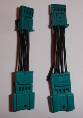
Now you need to make up a junction to split the power from each switch so that you get two new outputs to go to the two new LEDs.
What you are aiming for is a direct connection from the pin terminal uncoded 4 POL. 61136925611 to the socket housing uncoded 4 POL. 61138380696 for the pins you don't need. And a branch out for the two pins you need. These are Ground on pin 2 and +ve is on pin 3 in three doors, but in pin 4 in Driver door. I chose to make these connections on a small vero board and then covered it in heat shrink.
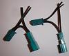

Take the two output wires for the LEDs and connect them up to four Pin-contact 0,2- 0,5MM? 61130005198. The LED at the bottom door may need some extension wire so that it reaches there.
Put on the two pin terminal uncoded 2 POL. 61138373583 to the pin contacts and then you can plug the LEDs into them.
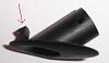
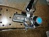
Making the holes in the doors are a pain, be very very careful when making the holes especially the one near the door handle because your drill bit can go through the handle if you are not careful. Start small and work your way slowly.
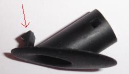
It may help to cut off the small catch on the LED exits to make it easier to mount but then you will need some glue to hold those in place.
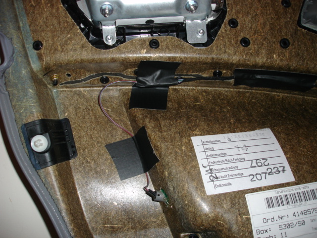
May sure you tape the new wiring carefully to the door and avoid the air bag routes.

That's it. Doing it this way you can always still remove the door panels and change any of the LEDs if they blow.
I'll just cover the bits that are missing from that DIY.
There are basically atleast two configuration for the doors.
1. Models with Door Modules.
2. Models without Door Modules.
Both the DIY linked and my car are the later versions without the door modules.
Don't bother putting any resistors in series with the LEDs because the signal is already current limited and adding resistors will just make the LEDs are lot dimmer.
Definately spend money and buy the OEM LEDs because they come in a housing that clicks into the openings and at the correct angle. The OEM LEDs also come with a 2 pin socket housing at the end.
Besides all the parts listed in that other DIY to make EACH door plug and play you need the following parts.
1. 1 x Universal socket housing uncoded 4 POL. 61138380696
2. 1 x Universal pin terminal uncoded 4 POL. 61136925611
3. 8 x Pin-contact 0,2- 0,5MM? 61130005198 - these come with about 1 foot of wire attached (or if you want to crimp things yourself you need 8 x 61131383672)
4. 4 x Bushing contact 0,2- 0,5MM? 61130005197 - these come with about 1 foot of wire attached (or if you want to crimp things yourself you need 4 x 61131383776)
5. 2 x Universal pin terminal uncoded 2 POL. 61138373583
Now you need to make up a junction to split the power from each switch so that you get two new outputs to go to the two new LEDs.
What you are aiming for is a direct connection from the pin terminal uncoded 4 POL. 61136925611 to the socket housing uncoded 4 POL. 61138380696 for the pins you don't need. And a branch out for the two pins you need. These are Ground on pin 2 and +ve is on pin 3 in three doors, but in pin 4 in Driver door. I chose to make these connections on a small vero board and then covered it in heat shrink.

Take the two output wires for the LEDs and connect them up to four Pin-contact 0,2- 0,5MM? 61130005198. The LED at the bottom door may need some extension wire so that it reaches there.
Put on the two pin terminal uncoded 2 POL. 61138373583 to the pin contacts and then you can plug the LEDs into them.
Making the holes in the doors are a pain, be very very careful when making the holes especially the one near the door handle because your drill bit can go through the handle if you are not careful. Start small and work your way slowly.
It may help to cut off the small catch on the LED exits to make it easier to mount but then you will need some glue to hold those in place.


May sure you tape the new wiring carefully to the door and avoid the air bag routes.

That's it. Doing it this way you can always still remove the door panels and change any of the LEDs if they blow.
 05-05-2009, 01:28 PM
#2
Senior Members
Join Date: Jun 2007
Location: Milton Keynes, United Kingdom
Posts: 336
Likes: 0
Received 0 Likes
on
0 Posts
Originally Posted by bruce_miranda' post='868904' date='May 5 2009, 09:06 PM
Please read this thread in conjunction with this one http://forums.e60.net/index.php?showtopic=61259&hl= because he did it first. I just made it plug and play.
I'll just cover the bits that are missing from that DIY.
There are basically atleast two configuration for the doors.
1. Models with Door Modules.
2. Models without Door Modules.
Both the DIY linked and my car are the later versions without the door modules.
Don't bother putting any resistors in series with the LEDs because the signal is already current limited and adding resistors will just make the LEDs are lot dimmer.
Definately spend money and buy the OEM LEDs because they come in a housing that clicks into the openings and at the correct angle. The OEM LEDs also come with a 2 pin socket housing at the end.
Besides all the parts listed in that other DIY to make EACH door plug and play you need the following parts.
1. 1 x Universal socket housing uncoded 4 POL. 61138380696
2. 1 x Universal pin terminal uncoded 4 POL. 61136925611
3. 8 x Pin-contact 0,2- 0,5MM? 61130005198 - these come with about 1 foot of wire attached (or if you want to crimp things yourself you need 8 x 61131383672)
4. 4 x Bushing contact 0,2- 0,5MM? 61130005197 - these come with about 1 foot of wire attached (or if you want to crimp things yourself you need 4 x 61131383776)
5. 2 x Universal pin terminal uncoded 2 POL. 61138373583
Now you need to make up a junction to split the power from each switch so that you get two new outputs to go to the two new LEDs.
What you are aiming for is a direct connection from the pin terminal uncoded 4 POL. 61136925611 to the socket housing uncoded 4 POL. 61138380696 for the pins you don't need. And a branch out for the two pins you need. These are Ground on pin 2 and +ve is on pin 3 in three doors, but in pin 4 in Driver door. I chose to make these connections on a small vero board and then covered it in heat shrink.
Attachment 78748 Attachment 78749
Take the two output wires for the LEDs and connect them up to four Pin-contact 0,2- 0,5MM? 61130005198. The LED at the bottom door may need some extension wire so that it reaches there.
Put on the two pin terminal uncoded 2 POL. 61138373583 to the pin contacts and then you can plug the LEDs into them.
Making the holes in the doors are a pain, be very very careful when making the holes especially the one near the door handle because your drill bit can go through the handle if you are not careful. Start small and work your way slowly.
It may help to cut off the small catch on the LED exits to make it easier to mount but then you will need some glue to hold those in place.
Attachment 78750
Attachment 78751
Attachment 78752
Attachment 78753
May sure you tape the new wiring carefully to the door and avoid the air bag routes.
Attachment 78755
Attachment 78756
That's it. Doing it this way you can always still remove the door panels and change any of the LEDs if they blow.
05-06-2009, 04:18 AM
#4
Contributors
Thread Starter
Join Date: Nov 2005
Location: London, UK
Posts: 4,719
Likes: 0
Received 3 Likes
on
3 Posts
My Ride: BMW E60 520d SE Saloon M47 2.0dTitanium Grey II, Grey−Dakota Leather, Visibility Package, Media Package, Through Load System, Lumbar support − fr seats, Automatic Air Conditioning−Advanced, High beam assistant, Hi−Fi Loudspeak
Model Year: 2006
Originally Posted by BlaSTiWi' post='869111' date='May 6 2009, 12:27 AM
How do you do the rear doors? The same way?
Just be careful that the driver's door is the only door where the +ve is on a different pin.
05-08-2009, 08:07 AM
#5
Members
Senior Members
Join Date: Sep 2006
Location: Omaha, NE - USA
Posts: 3,238
Likes: 0
Received 1 Like
on
1 Post
My Ride: MY07 525xi Silver Gray
Model Year: 2007
Bruce,
I'm a bit confuse... on each door I'll end up 2 pair of led wires (handle & pocket), right? I just parallel them into a pair of + & -, right?
I can picture the junction using part #1 & #2 w/ 4 wires from part #3 and wires from part #4 now use the 4 leftover wires from part #3 w/ part #5 (2-each) a pair from the led and the other pair from the junction?
I guess I'm not sure w/ part #5 look like...
Tkx!
Originally Posted by bruce_miranda' post='868904' date='May 5 2009, 03:06 PM
[...]
Besides all the parts listed in that other DIY to make EACH door plug and play you need the following parts.
1. 1 x Universal socket housing uncoded 4 POL. 61138380696
2. 1 x Universal pin terminal uncoded 4 POL. 61136925611
3. 8 x Pin-contact 0,2- 0,5MM? 61130005198 - these come with about 1 foot of wire attached (or if you want to crimp things yourself you need 8 x 61131383672)
4. 4 x Bushing contact 0,2- 0,5MM? 61130005197 - these come with about 1 foot of wire attached (or if you want to crimp things yourself you need 4 x 61131383776)
5. 2 x Universal pin terminal uncoded 2 POL. 61138373583
Now you need to make up a junction to split the power from each switch so that you get two new outputs to go to the two new LEDs.
What you are aiming for is a direct connection from the pin terminal uncoded 4 POL. 61136925611 to the socket housing uncoded 4 POL. 61138380696 for the pins you don't need. And a branch out for the two pins you need. These are Ground on pin 2 and +ve is on pin 3 in three doors, but in pin 4 in Driver door. I chose to make these connections on a small vero board and then covered it in heat shrink.
Attachment 78748 Attachment 78749
Take the two output wires for the LEDs and connect them up to four Pin-contact 0,2- 0,5MM? 61130005198. The LED at the bottom door may need some extension wire so that it reaches there.
Put on the two pin terminal uncoded 2 POL. 61138373583 to the pin contacts and then you can plug the LEDs into them.
Making the holes in the doors are a pain, be very very careful when making the holes especially the one near the door handle because your drill bit can go through the handle if you are not careful. Start small and work your way slowly.
It may help to cut off the small catch on the LED exits to make it easier to mount but then you will need some glue to hold those in place.
[...pics...]
May sure you tape the new wiring carefully to the door and avoid the air bag routes.
[...pics...]
That's it. Doing it this way you can always still remove the door panels and change any of the LEDs if they blow.
05-08-2009, 10:06 AM
#6
Contributors
Thread Starter
Join Date: Nov 2005
Location: London, UK
Posts: 4,719
Likes: 0
Received 3 Likes
on
3 Posts
My Ride: BMW E60 520d SE Saloon M47 2.0dTitanium Grey II, Grey−Dakota Leather, Visibility Package, Media Package, Through Load System, Lumbar support − fr seats, Automatic Air Conditioning−Advanced, High beam assistant, Hi−Fi Loudspeak
Model Year: 2006

Any clearer now? NOTE : This diagram is for all door except the Driver which has the +ve on the 4th pin. The pins and socket contacts are used inside the plugs.
05-09-2009, 07:35 AM
#7
Contributors
Thread Starter
Join Date: Nov 2005
Location: London, UK
Posts: 4,719
Likes: 0
Received 3 Likes
on
3 Posts
My Ride: BMW E60 520d SE Saloon M47 2.0dTitanium Grey II, Grey−Dakota Leather, Visibility Package, Media Package, Through Load System, Lumbar support − fr seats, Automatic Air Conditioning−Advanced, High beam assistant, Hi−Fi Loudspeak
Model Year: 2006

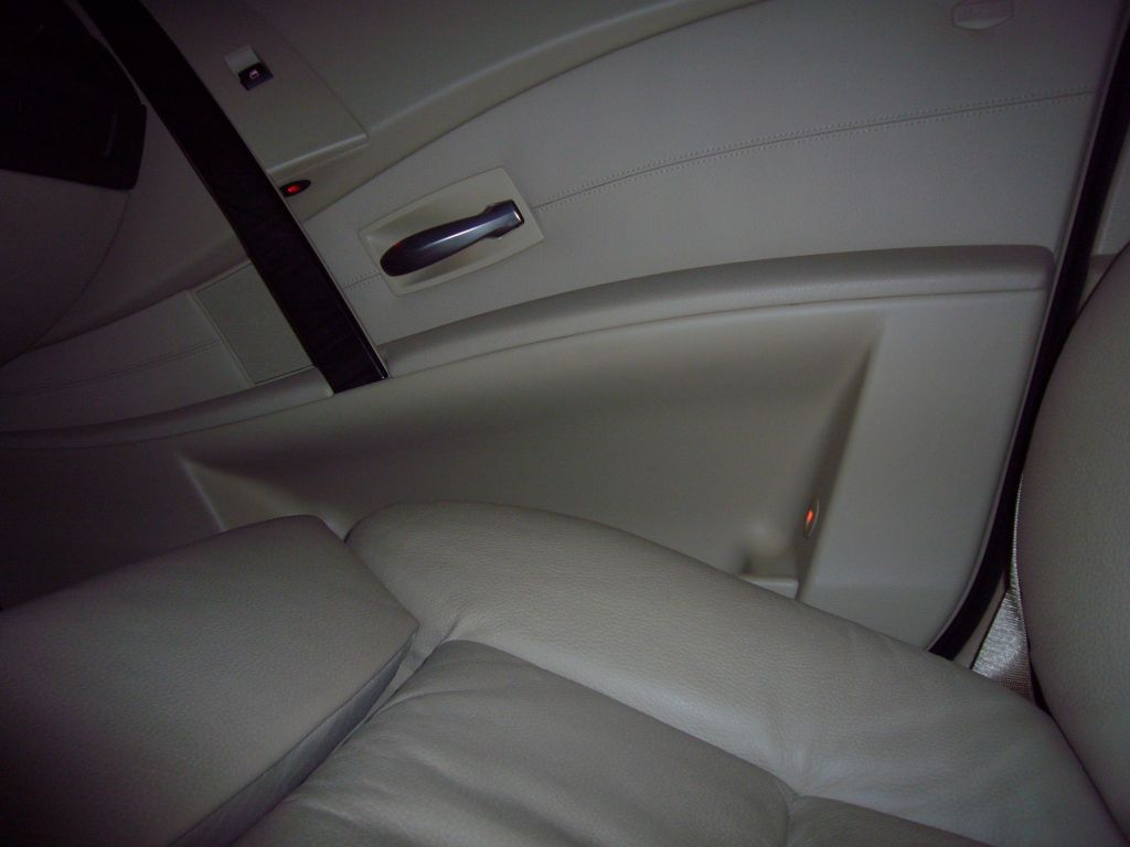

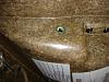
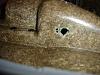
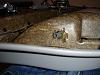
Photos of the finished job.
Note : the leds above the door pocket need to point downwards into the door pockets.

 06-03-2009, 10:52 AM
#9
Members
Join Date: Apr 2008
Location: UK
Posts: 100
Likes: 0
Received 0 Likes
on
0 Posts
My Ride: 2005 E61 525d M-Sport, Titanium Silver, Black Dakota Leather, Media Pack, Sun Protection Glass, M6 Staggered Alloys, ACS Rear Diffuser, EBC Green Stuff Brake Pads, I-Pod Interface. Rear Aux Power DIY, LCI Rear Lights, Extended interior lights - doors and footwells, LED licence plate lights.
Thanks Bruce and Vesil for posting this DIY.
I have just received all the parts to carry out the install, but I am unclear of the orientation of the rear door pocket light.
Would someone with the extended light feature be able to post a photo of their rear door pocket light so I can work out / see which way round it should be fitted.
Many thanks in advance.
I have just received all the parts to carry out the install, but I am
unclear of the orientation of the rear door pocket light. Would someone with the extended light feature be able to post a photo of their rear door pocket light so I can work out / see which way round it should be fitted.
Many thanks in advance.
06-03-2009, 11:39 AM
#10
Contributors
Thread Starter
Join Date: Nov 2005
Location: London, UK
Posts: 4,719
Likes: 0
Received 3 Likes
on
3 Posts
My Ride: BMW E60 520d SE Saloon M47 2.0dTitanium Grey II, Grey−Dakota Leather, Visibility Package, Media Package, Through Load System, Lumbar support − fr seats, Automatic Air Conditioning−Advanced, High beam assistant, Hi−Fi Loudspeak
Model Year: 2006
Originally Posted by kErb' post='899623' date='Jun 3 2009, 07:52 PM
Thanks Bruce and Vesil for posting this DIY.
I have just received all the parts to carry out the install, but I am unclear of the orientation of the rear door pocket light.
Would someone with the extended light feature be able to post a photo of their rear door pocket light so I can work out / see which way round it should be fitted.
Many thanks in advance.
I have just received all the parts to carry out the install, but I am
unclear of the orientation of the rear door pocket light. Would someone with the extended light feature be able to post a photo of their rear door pocket light so I can work out / see which way round it should be fitted.
Many thanks in advance.